
user manual


Table Of Contents
- Chapter 1 Overview
- Chapter 2 Locations and Functions of Parts and Controls
- Chapter 3 Setting Up the VTR
- Chapter 4 Menu Settings
- 4-1 Registering and Storing Menu Settings
- 4-2 HOME Menu
- 4-2-1 Selecting the Output Signals(PB/EE)
- 4-2-2 Record Inhibit Mode (REC INH)
- 4-2-3 Selecting the Edit Mode and Edit Channel (ASSEMBLE or INS CUE)
- 4-2-4 Preread Settings (PRE READ)
- 4-2-5 Still-Picture Output (FREEZE)
- 4-2-6 Selecting the Capstan Servo Lock Mode (CAP LOCK)
- 4-2-7 Setting the Preroll Time (PREROLL TIME)
- 4-2-8 Selecting DMC Playback (DMC)
- 4-2-9 Recalling Edit Points (LAST EDIT)
- 4-3 TC Menu
- 4-3-1 Setting the Time Data (TIMER SEL/RESET/SET/HOLD)
- 4-3-2 Setting the Time Code Reader (TCR SEL)
- 4-3-3 Setting the Time Code Generator (TCG SOURCE/MODE)
- 4-3-4 Selecting the Time Code Running Mode (RUN MODE)
- 4-3-5 Selecting the Drop Frame Mode (DF/NDF)
- 4-3-6 Inserting VITC input source (VITC)
- 4-3-7 Selecting CTL Display Mode (TAPE TIMER)
- 4-3-8 Presetting Pull Down Time Code (PDPSET MENU)(when HKDV-507/507D is installed)
- 4-3-9 Presetting for Conversion From 24-frame Into 25-frame Time Code
- 4-3-10 Conversion of Time Code During Playback in 25F Mode (TC CONV)
- 4-3-11 Displaying the Pull Down Time Code (when HKDV-507/507D is installed)
- 4-3-12 Superimposition of Character Information (PD CHARA/CHARA SUPER/H-POS/V-POS)
- 4-3-13 Setting the VITC Insertion Line (VITC POS-1/POS-2)
- 4-3-14 Presetting for Conversion From 25-frame Into 24-frame Time Code
- 4-3-15 Conversion of Time Code During Playback in 24F Mode (TC CONV)
- 4-4 CUE Menu
- 4-5 PF1 Menu (Factory Settings)
- 4-6 PF2 Menu (Factory Settings)
- 4-7 SET UP Menu
- Chapter 5 Recording/Playback
- 5-1 Preparing for Recording
- 5-2 Recording
- 5-3 Preparing for Playback
- 5-3-1 Setting Switches and Menus
- 5-3-2 Adjusting the Audio Playback Level
- 5-3-3 Selecting the HD-SD Conversion Mode (when HKDV-501A is installed)
- 5-3-4 Selecting the Conversion Mode of the Effective Scanning Line Number
- 5-3-5 Improving the Vertical Resolution during Slow-Motion Playback (when HKDV-502 is installed)
- 5-4 Playback
- Chapter 6 Editing
- Appendix
- Maintenance
- Specifications
- Operation Information Display
- Error Messages and Warning Messages
- Glossary
- Menu List
- Items Related to the Hours Meter (H01~)
- Items Related to VTR Operations (001~)
- Items Related to Operation Panels (101~)
- Items Related to Remote Interface (201~)
- Items Related to Editing (301~)
- Items Related to Prerolling (401~)
- Items Related to Recording Protection (501~)
- Items Related to the Time Code (601~)
- Items Related to the Video Control (701~)
- Items Related to the Audio Control (801~)
- Items Related to Digital Processing (901~)
- Items Related to the Pull Down Control (A01~)
- Other Items (T01~)
- Index
- Table of Functions (Factory Default Settings)
Chapter 2 Locations and Functions of Parts and Controls 2-3
Chapter 2 Locations and Functions of Parts and Controls
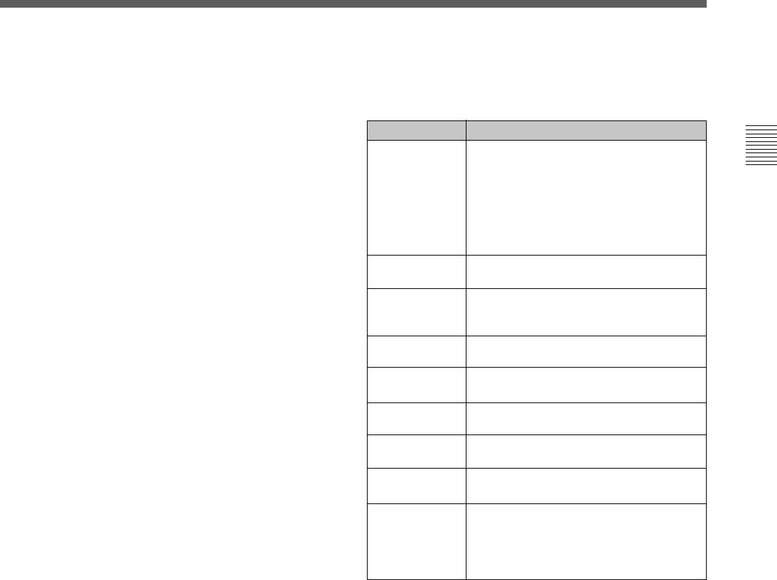
9 Indicator window
The following indicators light up to indicate the VTR’s
status.
4 PHONES level control
Adjusts the output level to the PHONES jack.
You can enable this control to simultaneously adjust
the output level to the MONITOR OUTPUT
connectors on the connector panel.
For details, see Section 5-1-2, “Selecting Audio Signals” on
page 5-2.
5 PB (playback) level controls
Adjust the level of the audio output for channels 1 to 4
and the cue channel.
Pull out the controls during playback to adjust the
audio output for each channel. Push in again for
factory-set levels (+4 dB output for a signal recorded
at a reference level of 0 dB). When pushed in, the
controls cannot adjust the audio output level.
6 REC (recording) level controls
Adjust the recording level for channels 1 to 4 and the
cue channel.
Pull out the controls to adjust the recording level for
each channel in E-E mode
1)
. Push in again for the
factory-set recording level (0 dB reference level for an
input of +4 dB). When pushed in, the controls cannot
adjust the recording level.
7 Audio level meters
Indicate the recording level in recording or E-E mode
or the playback level in playback or CONFI mode.
The display range can be changed by pressing the
DISPLAY FULL/FINE button. The reference level is
factory set at –20 dB, and the peak level at 0 dB.
8 MONITOR SELECT button
Selects the audio signal to be output at the MONITOR
OUTPUT L/R connector(s). Press to light the button
up, then press the AUDIO INPUT/MONITOR
SELECT button(s) to specify which channel(s) are to
be monitored at the MONITOR OUTPUT L or R
connector. If you specify more than one channel to the
same MONITOR OUTPUT connector, a mixed audio
signal is output from that connector. This specification
can also be done with setting the VTR SETUP menu
807~808 AUDIO MONITOR L~R select .
For details, see Section 4-6-3, “Selecting the Monitor
Output Signal (MON-L SEL/MON-R SEL)” on page 4-58.
1) E-E mode
An abbreviation for Electric-to-Electric mode. In this
mode, video or audio input signals are passed and output
..........................................................................................................................................................................................................
Indicator Status
Indicators and corresponding VTR status
CHANNEL
CONDITION
Indicates the playback signal condition.
Green: Playback signal is good.
Yellow: Playback signal is less than
good, but still reproducible.
Red: Playback signal is poor. Head
cleaning or internal inspection is
necessary if the indicator lights up
continuously.
INTERLACE Lights when the VTR is operating under
the interlace mode(50i/59.94i/60i).
PsF Lights when the VTR is operating under
the PsF mode(23.98PsF/24PsF/25PsF/
29.97PsF/30PsF).
23.98 Lights when the VTR is operating with a
frame frequency of 23.98 Hz.
25 Lights when the VTR is operating with a
frame frequency of 25 Hz.
24 Lights when the VTR is operating with a
frame frequency of 24 Hz.
29.97 Lights when the VTR is operating with a
frame frequency of 29.97 Hz.
only through the VTR’s internal circuitry, and not
through the magnetic conversion system comprising tape
and heads.
30
Lights when the VTR is operating with a
frame frequency of 30 Hz.
For more information about the selection of the frame
frequency , refer to the supplied Maintenance Manual.
ADV. AUDIO
Lights when item 821.AUDIO ADVANCE
MODE in the VTR SETUP menu is set to
“on.” When edit preset is set to “ON”, the
HDW-F500 operates internally with “off”
setting, so this indicator lights off.