
user manual


Table Of Contents
- Chapter 1 Overview
- Chapter 2 Locations and Functions of Parts and Controls
- Chapter 3 Setting Up the VTR
- Chapter 4 Menu Settings
- 4-1 Registering and Storing Menu Settings
- 4-2 HOME Menu
- 4-2-1 Selecting the Output Signals(PB/EE)
- 4-2-2 Record Inhibit Mode (REC INH)
- 4-2-3 Selecting the Edit Mode and Edit Channel (ASSEMBLE or INS CUE)
- 4-2-4 Preread Settings (PRE READ)
- 4-2-5 Still-Picture Output (FREEZE)
- 4-2-6 Selecting the Capstan Servo Lock Mode (CAP LOCK)
- 4-2-7 Setting the Preroll Time (PREROLL TIME)
- 4-2-8 Selecting DMC Playback (DMC)
- 4-2-9 Recalling Edit Points (LAST EDIT)
- 4-3 TC Menu
- 4-3-1 Setting the Time Data (TIMER SEL/RESET/SET/HOLD)
- 4-3-2 Setting the Time Code Reader (TCR SEL)
- 4-3-3 Setting the Time Code Generator (TCG SOURCE/MODE)
- 4-3-4 Selecting the Time Code Running Mode (RUN MODE)
- 4-3-5 Selecting the Drop Frame Mode (DF/NDF)
- 4-3-6 Inserting VITC input source (VITC)
- 4-3-7 Selecting CTL Display Mode (TAPE TIMER)
- 4-3-8 Presetting Pull Down Time Code (PDPSET MENU)(when HKDV-507/507D is installed)
- 4-3-9 Presetting for Conversion From 24-frame Into 25-frame Time Code
- 4-3-10 Conversion of Time Code During Playback in 25F Mode (TC CONV)
- 4-3-11 Displaying the Pull Down Time Code (when HKDV-507/507D is installed)
- 4-3-12 Superimposition of Character Information (PD CHARA/CHARA SUPER/H-POS/V-POS)
- 4-3-13 Setting the VITC Insertion Line (VITC POS-1/POS-2)
- 4-3-14 Presetting for Conversion From 25-frame Into 24-frame Time Code
- 4-3-15 Conversion of Time Code During Playback in 24F Mode (TC CONV)
- 4-4 CUE Menu
- 4-5 PF1 Menu (Factory Settings)
- 4-6 PF2 Menu (Factory Settings)
- 4-7 SET UP Menu
- Chapter 5 Recording/Playback
- 5-1 Preparing for Recording
- 5-2 Recording
- 5-3 Preparing for Playback
- 5-3-1 Setting Switches and Menus
- 5-3-2 Adjusting the Audio Playback Level
- 5-3-3 Selecting the HD-SD Conversion Mode (when HKDV-501A is installed)
- 5-3-4 Selecting the Conversion Mode of the Effective Scanning Line Number
- 5-3-5 Improving the Vertical Resolution during Slow-Motion Playback (when HKDV-502 is installed)
- 5-4 Playback
- Chapter 6 Editing
- Appendix
- Maintenance
- Specifications
- Operation Information Display
- Error Messages and Warning Messages
- Glossary
- Menu List
- Items Related to the Hours Meter (H01~)
- Items Related to VTR Operations (001~)
- Items Related to Operation Panels (101~)
- Items Related to Remote Interface (201~)
- Items Related to Editing (301~)
- Items Related to Prerolling (401~)
- Items Related to Recording Protection (501~)
- Items Related to the Time Code (601~)
- Items Related to the Video Control (701~)
- Items Related to the Audio Control (801~)
- Items Related to Digital Processing (901~)
- Items Related to the Pull Down Control (A01~)
- Other Items (T01~)
- Index
- Table of Functions (Factory Default Settings)
Chapter 5 Recording/Playback 5-17
Chapter 5 Recording/Playback
1122
2345 6
1123 1124 1125
2134567
A
C1
23.976PsF
59.94i
D2 D1 D2 A1 A2 B1 B2 B1 C2 C1 D2 D1 D2
BCDAB
A
D1
23.976PsF
59.94i
D2 A1 A2 B1 B2 B1 C2 C1 D2 D1 D2
BCDAB
D1 D2 A1 A2 B1 B2 B1 C2 C1 D2 D1 D2
D1 D2 A1 A2 B1 B2 B1 C2 C1 D2 D1 D2
D1 D2 A1 A2 B1 B2 B1 C2 C1 D2 D1 D2
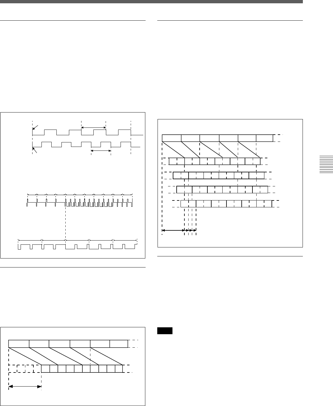
Phase lock for the HD reference signal
(23.98PsF) and 525 black burst signal
(59.94i mode)
When an optional HKDV-507D HD Pull Down Board
is installed and item A05. PD EXT SD REF LOCK
MODE in the VTR SETUP menu is set to “lock1” or
“lock2” to lock the pull down output signal to the
external reference signal, the phase of the external
reference signals for 24F mode and 30F mode should
be locked as illustrated below.
Pull down output phase lock
When an optional HKDV-507D HD Pull Down Board
is installed and item A05. PD EXT SD REF LOCK
MODE in the VTR SETUP menu is set to “lock2”,
the phase of the pull dowm otuput signal can be locked
as illustrated below.
HD SDI
or
external HD Ref.
Exetrnal SD Ref.
Line 1
1 frame
1 frameLine 4 ± 10 lines
•Tri-level sync signal
(1125/59.94i)
•3.58 black burst signal
(525/59/94i)
2 frames delay
(59.94i)
Output delay
When an optional HKDV-507 HD Pull Down Board is
installed, or when an optional HKDV-507D HD Pull
Down Board is installed and item A05. PD EXT SD
REF LOCK MODE in the VTR SETUP menu is set to
“off” or “lock1,” the phase of the output delay for
conversion is as illustrated below.
However, when the HKDV-507D board is installed
and item A05 is set to “lock1,” pull down output is
locked to the external reference signal (525 black burst
signal).
Pull down audio output
Audio signal multiplexed to the pull down HD SDI
output signal is delayed so that the audio signal and the
video signal are equal in phase as considering the
video signal delay due to video signal processing. The
pulled down and down-converted SDI output signal is
also multiplexed with the delayed audio signal.
Note
The AES/EBU or analog audio output signal and 24-
frame video output signal (the main output line of this
unit) are equal in phase.
A frame: No.2
A frame: No.1
A frame: No.0
A frame: No.3
Variable
delay