
user manual


Table Of Contents
- Chapter 1 Overview
- Chapter 2 Locations and Functions of Parts and Controls
- Chapter 3 Setting Up the VTR
- Chapter 4 Menu Settings
- 4-1 Registering and Storing Menu Settings
- 4-2 HOME Menu
- 4-2-1 Selecting the Output Signals(PB/EE)
- 4-2-2 Record Inhibit Mode (REC INH)
- 4-2-3 Selecting the Edit Mode and Edit Channel (ASSEMBLE or INS CUE)
- 4-2-4 Preread Settings (PRE READ)
- 4-2-5 Still-Picture Output (FREEZE)
- 4-2-6 Selecting the Capstan Servo Lock Mode (CAP LOCK)
- 4-2-7 Setting the Preroll Time (PREROLL TIME)
- 4-2-8 Selecting DMC Playback (DMC)
- 4-2-9 Recalling Edit Points (LAST EDIT)
- 4-3 TC Menu
- 4-3-1 Setting the Time Data (TIMER SEL/RESET/SET/HOLD)
- 4-3-2 Setting the Time Code Reader (TCR SEL)
- 4-3-3 Setting the Time Code Generator (TCG SOURCE/MODE)
- 4-3-4 Selecting the Time Code Running Mode (RUN MODE)
- 4-3-5 Selecting the Drop Frame Mode (DF/NDF)
- 4-3-6 Inserting VITC input source (VITC)
- 4-3-7 Selecting CTL Display Mode (TAPE TIMER)
- 4-3-8 Presetting Pull Down Time Code (PDPSET MENU)(when HKDV-507/507D is installed)
- 4-3-9 Presetting for Conversion From 24-frame Into 25-frame Time Code
- 4-3-10 Conversion of Time Code During Playback in 25F Mode (TC CONV)
- 4-3-11 Displaying the Pull Down Time Code (when HKDV-507/507D is installed)
- 4-3-12 Superimposition of Character Information (PD CHARA/CHARA SUPER/H-POS/V-POS)
- 4-3-13 Setting the VITC Insertion Line (VITC POS-1/POS-2)
- 4-3-14 Presetting for Conversion From 25-frame Into 24-frame Time Code
- 4-3-15 Conversion of Time Code During Playback in 24F Mode (TC CONV)
- 4-4 CUE Menu
- 4-5 PF1 Menu (Factory Settings)
- 4-6 PF2 Menu (Factory Settings)
- 4-7 SET UP Menu
- Chapter 5 Recording/Playback
- 5-1 Preparing for Recording
- 5-2 Recording
- 5-3 Preparing for Playback
- 5-3-1 Setting Switches and Menus
- 5-3-2 Adjusting the Audio Playback Level
- 5-3-3 Selecting the HD-SD Conversion Mode (when HKDV-501A is installed)
- 5-3-4 Selecting the Conversion Mode of the Effective Scanning Line Number
- 5-3-5 Improving the Vertical Resolution during Slow-Motion Playback (when HKDV-502 is installed)
- 5-4 Playback
- Chapter 6 Editing
- Appendix
- Maintenance
- Specifications
- Operation Information Display
- Error Messages and Warning Messages
- Glossary
- Menu List
- Items Related to the Hours Meter (H01~)
- Items Related to VTR Operations (001~)
- Items Related to Operation Panels (101~)
- Items Related to Remote Interface (201~)
- Items Related to Editing (301~)
- Items Related to Prerolling (401~)
- Items Related to Recording Protection (501~)
- Items Related to the Time Code (601~)
- Items Related to the Video Control (701~)
- Items Related to the Audio Control (801~)
- Items Related to Digital Processing (901~)
- Items Related to the Pull Down Control (A01~)
- Other Items (T01~)
- Index
- Table of Functions (Factory Default Settings)
5-16 Chapter 5 Recording/Playback
5-4 Playback
Chapter 5 Recording/Playback
$$$
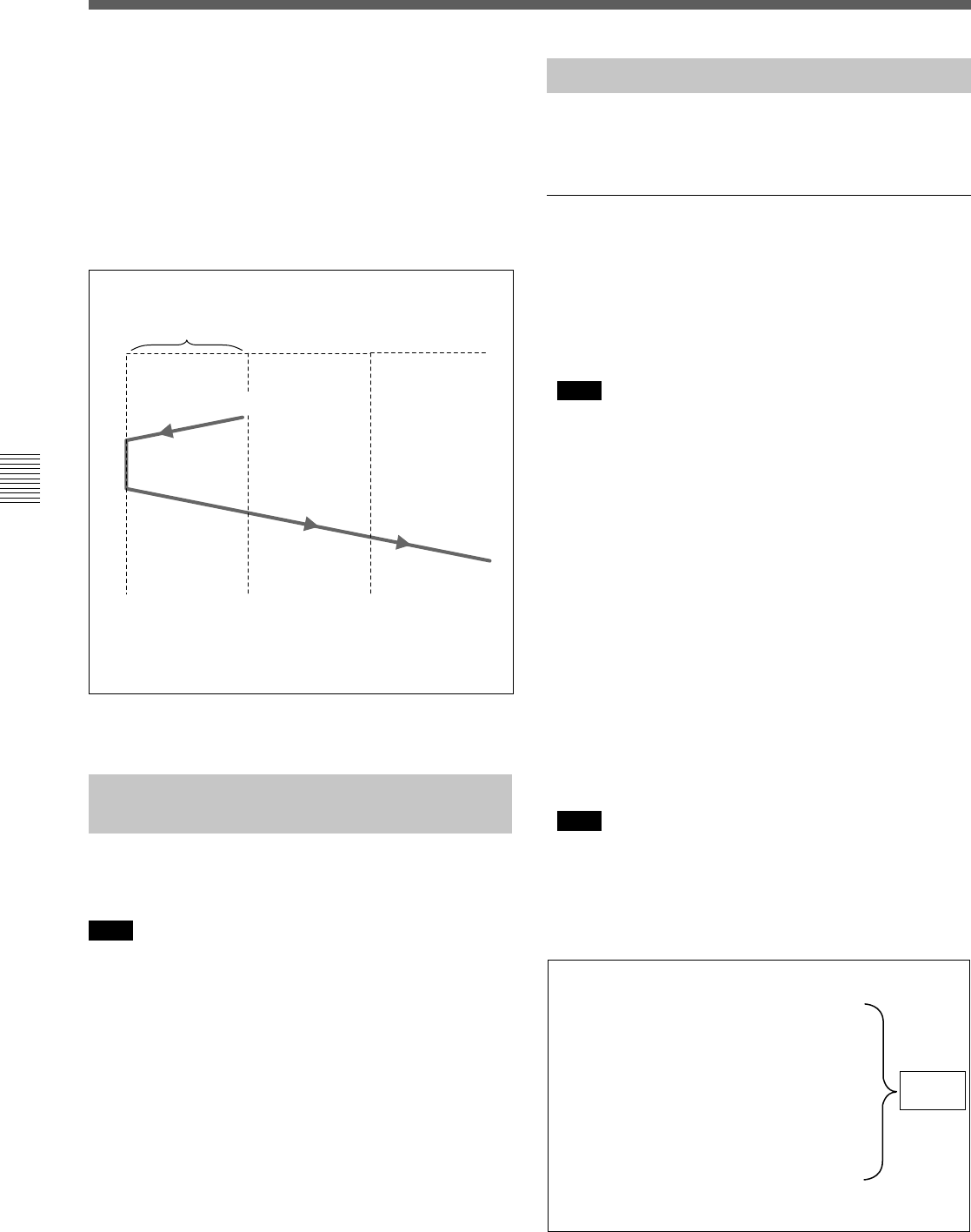
Press the PREVIEW button.
Preroll time ×
initial speed
IN point
Speed variation
end point
Tape runs at
initial speed
Playback mode
using the
memorized speed
Playback at
normal speed
To stop the tape during DMC playback
Press the STOP button.
To exit DMC playback mode
Press the ALT/[F7] (DMC) button in HOME menu to
go off DMC on the display.
During DMC playback, the tape runs as shown in the
diagram below.
DMC playback
5-4-5 Playing Back Non-audio
Data
Non-audio data recorded on a tape is detected
automatically and played back.
Note
When non-audio data is being played back:
• The “OVER” indication on the audio level meters
flashes.
• Analog audio output to the main line, monitor, and
the headphones are muted.
• The playback level cannot be adjusted using the PB
audio output level controls.
5-4-6 Output of Pull Down Signal
The explanation of pull down signal output for
playback is given below.
Time code multiplexed to pull down signal
output
• The value of the time code multiplexed to pull down
HD SDI output signal is determined by the time code
preset using the PDPSET MENU in the TC menu and
converted into 30-frame time code.
Note
LTC output of this unit is always 24-frame time code
which is output from the main output line of this unit.
• When this unit is operated in 24F mode, time code
data of the user’s bits area is not included in the pull
down signal output. The time code value before
conversion (24F mode) and sequence information of
conversion contained in user’s bits data are
multiplexed to the HD SDI output signal. The
following four bits are used for the sequence
information to display 0 to 9 repeatedly.
MSB: The first bit of the tens digit of the hour
The second bit of the tens digit of the hour
The first bit of the tens digit of the minute
LSB: The first bit of the tens digit of the second
When the sequence information is masked, the
remaining contents of user’s bits data are the same as
the time code value before conversion (24F mode).
Note
Since user’s bits data multiplexed to the down-
converted output signal are updated frame by frame,
24-frame time code and sequence information of the
down-converted output signal differs from those
multiplexed to the HD output signal.
00:00:00:00
00:00:00:00
00:00:00:01
00:00:00:01
00:00:00:02
00:00:00:02
00:00:00:03
00:00:00:03
00:00:00:04
00:00:00:04
00:00:00:05
00:00:00:05
00:00:00:00
00:00:80:00
00:80:00:01
00:80:80:01
40:00:00:01
40:00:80:02
40:80:00:02
40:80:80:03
80:00:00:03
80:00:80:03
00:00:00:04
00:00:80:04
*
*
*
*
*
*
Time code area
30F TC
User’s bits area (HD)
24F TC + sequence information
A frame
A frame
Cycle of
conversion