
user manual
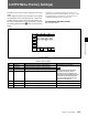


Table Of Contents
- Chapter 1 Overview
- Chapter 2 Locations and Functions of Parts and Controls
- Chapter 3 Setting Up the VTR
- Chapter 4 Menu Settings
- 4-1 Registering and Storing Menu Settings
- 4-2 HOME Menu
- 4-2-1 Selecting the Output Signals(PB/EE)
- 4-2-2 Record Inhibit Mode (REC INH)
- 4-2-3 Selecting the Edit Mode and Edit Channel (ASSEMBLE or INS CUE)
- 4-2-4 Preread Settings (PRE READ)
- 4-2-5 Still-Picture Output (FREEZE)
- 4-2-6 Selecting the Capstan Servo Lock Mode (CAP LOCK)
- 4-2-7 Setting the Preroll Time (PREROLL TIME)
- 4-2-8 Selecting DMC Playback (DMC)
- 4-2-9 Recalling Edit Points (LAST EDIT)
- 4-3 TC Menu
- 4-3-1 Setting the Time Data (TIMER SEL/RESET/SET/HOLD)
- 4-3-2 Setting the Time Code Reader (TCR SEL)
- 4-3-3 Setting the Time Code Generator (TCG SOURCE/MODE)
- 4-3-4 Selecting the Time Code Running Mode (RUN MODE)
- 4-3-5 Selecting the Drop Frame Mode (DF/NDF)
- 4-3-6 Inserting VITC input source (VITC)
- 4-3-7 Selecting CTL Display Mode (TAPE TIMER)
- 4-3-8 Presetting Pull Down Time Code (PDPSET MENU)(when HKDV-507/507D is installed)
- 4-3-9 Presetting for Conversion From 24-frame Into 25-frame Time Code
- 4-3-10 Conversion of Time Code During Playback in 25F Mode (TC CONV)
- 4-3-11 Displaying the Pull Down Time Code (when HKDV-507/507D is installed)
- 4-3-12 Superimposition of Character Information (PD CHARA/CHARA SUPER/H-POS/V-POS)
- 4-3-13 Setting the VITC Insertion Line (VITC POS-1/POS-2)
- 4-3-14 Presetting for Conversion From 25-frame Into 24-frame Time Code
- 4-3-15 Conversion of Time Code During Playback in 24F Mode (TC CONV)
- 4-4 CUE Menu
- 4-5 PF1 Menu (Factory Settings)
- 4-6 PF2 Menu (Factory Settings)
- 4-7 SET UP Menu
- Chapter 5 Recording/Playback
- 5-1 Preparing for Recording
- 5-2 Recording
- 5-3 Preparing for Playback
- 5-3-1 Setting Switches and Menus
- 5-3-2 Adjusting the Audio Playback Level
- 5-3-3 Selecting the HD-SD Conversion Mode (when HKDV-501A is installed)
- 5-3-4 Selecting the Conversion Mode of the Effective Scanning Line Number
- 5-3-5 Improving the Vertical Resolution during Slow-Motion Playback (when HKDV-502 is installed)
- 5-4 Playback
- Chapter 6 Editing
- Appendix
- Maintenance
- Specifications
- Operation Information Display
- Error Messages and Warning Messages
- Glossary
- Menu List
- Items Related to the Hours Meter (H01~)
- Items Related to VTR Operations (001~)
- Items Related to Operation Panels (101~)
- Items Related to Remote Interface (201~)
- Items Related to Editing (301~)
- Items Related to Prerolling (401~)
- Items Related to Recording Protection (501~)
- Items Related to the Time Code (601~)
- Items Related to the Video Control (701~)
- Items Related to the Audio Control (801~)
- Items Related to Digital Processing (901~)
- Items Related to the Pull Down Control (A01~)
- Other Items (T01~)
- Index
- Table of Functions (Factory Default Settings)

4-6 PF2 Menu (Factory Settings)
4-60 Chapter 4 Menu Settings
Chapter 4 Menu Settings
4-6-1 Selecting the Audio Input
Signal (A-IN CH-1~CH4)
Function buttons [F1] (A-IN CH1) to [F4] (A-IN CH4)
select the audio input signal for the various channels.
SDI: Selects the audio signal input through the HD
SDI INPUT connector.
AES/EBU: Selects the audio signal input through the
AUDIO INPUT (AES/EBU) connectors.
analg: Selects the audio signal input through the
AUDIO INPUT connectors.
[SDTI] (Only when the optional HKDV-506A SDTI
Board is installed.): When the SDTI signal input
to the SDTI (OPTION) IN connector is selected
for the input video signal, the audio signal input
to the SDTI (OPTION) IN connector is
automatically selected for the input audio signal as
well. SDTI is displayed and can not be changed.
4-6-2 Setting Emphasis
(EMPHASIS)
To apply emphasis to a digital audio signal that has
been converted from an analog input audio signal, set
the [F7] (EMPHASIS) button to on.
4-6-3 Selecting the Monitor
Output Signal (MON-L SEL/MON-
R SEL)
The [F9] (MON-L SEL) and [F10] (MON-R SEL)
buttons allow you to specify the audio channel to be
output from the left and right MONITOR OUTPUT
connectors, respectively.
1: Audio channel 1
2: Audio channel 2
3: Audio channel 3
4: Audio channel 4
5: Analog cue channel
When multiple channels are selected for a single
connector, all of the numbers are displayed.
Select the output signal to be monitored as follows:
Making the setting
Follow the steps below to set the monitor output
signal.
1 Press the [F9] (MON-L SEL) or [F10] (MON-R
SEL) button.
The setting display section lights up.
2 Press numeric buttons 1 to 4 to select audio
channels 1 to 4, or numeric button 5 for the analog
cue channel.
Example: Pressing numeric buttons 1 and 2 selects
audio channels 1 and 2, leaving audio channels 3
and 4, and the analog cue channel off.
“12...” appears in the display.
3 To set the entered audio channels, press the
respective function button ([F9] or [F10]).