XR-4803 SERVICE MANUAL East European Model Model Name Using Similar Mechanism Tape Transport Mechanism Type NEW MG-25F-136 SPECIFICATIONS – Continued on next page – FM/MW/LW CASSETTE CAR STEREO MICROFILM
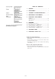
TABLE OF CONTENTS 1. GENERAL ................................................................... 3 2. DISASSEMBLY ......................................................... 9 3. ASSEMBLY OF MECHANISM DECK ........... 11 4. MECHANICAL ADJUSTMENTS ....................... 14 5. ELECTRICAL ADJUSTMENTS Test Mode ........................................................................ 14 Tape Deck Section .......................................................... 14 Tuner Section .........................
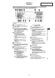
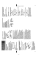
SECTION 1 GENERAL –3– This section is extracted from instruction manual.
–4–
–5–
–6–
–7–
–8–
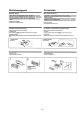
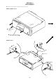
SECTION 2 DISASSEMBLY Note: Follow the disassembly procedure in the numerical order given. FRONT PANEL ASS’Y 1 Push the button (release). A 2 Remove the front panel ass’y to the direction of the arrow A.
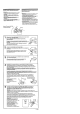
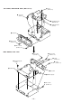
SUB PANEL, MECHANISM DECK (MG-25F-136) 5 screw (PTT2.6 × 6) 3 connector (CN351) 6 mechanism deck (MG-25F-136) 4 flexible flat cable (CN301) 2 sub panel 1 three screws (PTT2.6 × 8) 1 three screws (PTT2.6 × 8) MAIN BOARD, HEAT SINK 5 two screws (PTT2.6 × 5) 5 three screws (PTT2.6 × 10) 1 screw (PTT2.6 × 8) 3 two ground point screws 5 screw (PTT2.6 × 8) 4 main board 6 heat sink 2 rubber cap (25) 1 two screws (PTT2.
SECTION 3 ASSEMBLY OF MECHANISM DECK Note: Follow the assembly procedure in the numerical order given. 7 Holder the hanger by bending the claw. HOUSING 5 Fit projection on C part. 1 Install the catch to the hanger. 2 Install the hanger onto two claws of the housing. hanger 4 Fit claw on B part. 3 Put the housing under A part. 6 Fit projection on D part. housing C part 8 Hold the hanger by bending the claw.
LEVER (LDG-A) / (LDG-B) shaft A shaft B shaft C shaft A shaft B 1 Fit the lever (LDG-A) on shafts A – C and install it. 3 type-E stop ring 2.0 2 Fit the lever (LDG-B) on shafts A and B and install it. GEAR (LDG-FT) gear (LDG-D) 6 polyethylene washer hole hole 5 gear (LDG-FT) lever (LDG-A) gear (LDG-FB) 4 Align hole in the gear (LDG-D) with hole the lever (LDG-A). 1 2 tension spring (LD-2) 2 tension spring (LD-1) – 12 – 3 Move the lever (LDG-B) in the arrow direction.
GUIDE (C) 2 guide (C) 1 three claws – 13 –
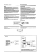
SECTION 4 MECHANICAL ADJUSTMENTS SECTION 5 ELECTRICAL ADJUSTMENTS 1. Clean the following parts with a denatured-alcohol-moistened swab: playback head pinch roller rubber belt capstan idler 2. Demagnetize the playback head with a head demagnetizer. 3. Do not use a magnetized screwdriver for the adjustments. 4. After the adjustments, apply suitable locking compound to the parts adjusted. 5. The adjustments should be performed with the power supply voltage unless otherwise noted.
TUNER SECTION FM Stereo Separation Adjustment Setting: [SOURCE] button: FM 0 dB=1 µV Cautions during repair When the tuner unit is defective, replace it by a new one because its internal block is difficult to repair. FM RF signal generator 1. FM Auto Scan/Stop Level Adjustment. 2. FM Stereo Separation Adjustment. 3. AM (MW) Auto Scan/Stop Level Adjustment. + – set Carrier frequency Output level Mode Modulation FM Auto Scan/Stop Level Adjustment Setting: [SOURCE] button: FM : 98.
AM (MW) Auto Scan/Stop Level Adjustment Make this adjustment after “FM Auto Scan/Stop Level Adjustment”. Setting: [SOURCE] and [MODE] button: MW Adjustment Location: —SET UPPER VIEW– Tape Speed Adjustment 30 Ω 15 pF 65 pF AM RF signal generator AM dummy antenna (50 Ω) Carrier frequency : 999 kHz 30% amplitude modulation by 1 kHz signal Output level : 33 dB (44.7 µV) set antenna jack (J1) TU1 Procedure: 1. Set to the test mode. (See page 14.) 2. Push the [SOURCE] button and set to FM. 3.
SECTION 6 DIAGRAMS 6-1. IC PIN FUNCTION DESCRIPTION • MAIN BOARD IC501 µPD17707GC-529-3B9 (SYSTEM CONTROLLER) Pin No.
Pin No.
Pin No.
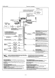
• IC Block Diagrams – MAIN Board – AUXIN2 DIREF LINEOUT2 NC 26 25 24 23 22 21 8 OUT2 IN2 2 24dB T2 VCC 3 + – 20 MSMODE – + NR BIAS PBFB2 31 PBRIN2 32 MS MODE X1 TAPE/AUX VCT 35 PBGND 36 VCT MS ON/ 15 NC OFF DETECT VCC + LPF + – 14 MSOUT PBFIN1 37 F3 F1 PBREF1 38 13 DGND X1 PBRIN1 39 PBFB1 40 12 MSTC + – 8 9 NC NC 6 10 G2FB 7 LINEOUT1 24dB MSLPF 4 5 TAPEIN1 AUXIN1 PBOUT1 3 VCC 2 PBEQ1 120µ/70µ 1 11 G1FB – + T1 LVRIN LCOM LT1 LT2 LT3 LTOUT LSIN LS1 LS2 LS3
IC611 BA3918-V2 REGULATOR OVER VOLTAGE PROTECT VCC 10 11 12 GND VDD AMP 9 FM NC 8 AM 7 ANT 6 COM 5 MODE2 MODE1 STB + – 2 3 4 + – 1 + – – + – 32 –
SECTION 7 EXPLODED VIEWS NOTE: • -XX and -X mean standardized parts, so they may have some difference from the original one. • Color Indication of Appearance Parts Example: KNOB, BALANCE (WHITE) . . . (RED) ↑ ↑ Parts Color Cabinet's Color • Items marked “*” are not stocked since they are seldom required for routine service. Some delay should be anticipated when ordering these items. • The mechanical parts with no reference number in the exploded views are not supplied.
(2) FRONT PANEL SECTION 102 #5 not supplied (KEY board) #5 108 109 117 120 107 118 116 106 105 111 115 114 121 LCD901 112 104 103 113 101 Ref. No. 101 102 103 104 105 * 106 107 108 109 111 Part No. Description 3-018-799-01 3-015-036-01 3-016-924-01 3-009-304-01 3-932-475-01 BUTTON (D-BASS) CUSHION (BACK PANEL) BUTTON (L) (2) (+.
(3) MECHANISM DECK SECTION (MG-25F-136) 160 159 163 158 A 155 161 HP901 154 162 157 #6 M901 156 A 164 153 152 165 #7 168 168 166 167 151 Ref. No. Part No.
SECTION 8 ELECTRICAL PARTS LIST KEY NOTE: • Due to standardization, replacements in the parts list may be different from the parts specified in the diagrams or the components used on the set. • -XX and -X mean standardized parts, so they may have some difference from the original one. • RESISTORS All resistors are in ohms. METAL: Metal-film resistor. METAL OXIDE: Metal oxide-film resistor. F: nonflammable Ref. No. Part No.
KEY Ref. No. Part No. Description Remark R956 R962 R963 1-216-049-11 RES, CHIP 1-216-025-00 RES, CHIP 1-216-033-00 METAL CHIP 1K 100 220 5% 5% 5% 1/10W 1/10W 1/10W R964 R965 R967 R968 R981 1-216-035-00 1-216-035-00 1-216-035-00 1-216-033-00 1-216-655-11 METAL CHIP METAL CHIP METAL CHIP METAL CHIP METAL CHIP 270 270 270 220 1.5K 5% 5% 5% 5% 0.
MAIN Ref. No. Part No. Description C358 C359 C501 C502 1-163-251-11 1-164-489-11 1-163-235-11 1-163-234-11 CERAMIC CHIP CERAMIC CHIP CERAMIC CHIP CERAMIC CHIP 100PF 0.22uF 22PF 20PF 5% 10% 5% 5% 50V 16V 50V 50V Remark C503 C504 C505 C551 C552 1-124-584-00 1-164-004-11 1-163-077-00 1-125-701-11 1-124-584-00 ELECT CERAMIC CHIP CERAMIC CHIP DOUBLE LAYER ELECT 100uF 0.1uF 0.1uF 0.047F 100uF 20% 10% 10% 10V 25V 25V 5.
MAIN Ref. No. Part No.
MAIN Ref. No. Part No. Description R282 R283 R284 R285 1-216-073-00 1-216-081-00 1-216-129-00 1-216-089-00 METAL CHIP METAL CHIP METAL CHIP RES, CHIP 10K 22K 2.2M 47K 5% 5% 5% 5% 1/10W 1/10W 1/10W 1/10W Remark R286 R301 R302 R303 R304 1-216-033-00 1-216-079-00 1-216-097-00 1-216-065-00 1-216-077-00 METAL CHIP METAL CHIP RES, CHIP METAL CHIP METAL CHIP 220 18K 100K 4.
Ref. No. Part No. Description Remark ************** HARDWARE LIST ************** #1 #2 #3 #4 #5 7-621-772-10 7-685-793-09 7-685-792-09 7-685-794-09 7-685-106-19 SCREW +B 2X4 SCREW +PTT 2.6X8 (S) SCREW +PTT 2.6X6 (S) SCREW +PTT 2.6X10 (S) SCREW +P 2X10 TYPE2 NON-SLIT #6 7-624-104-04 STOP RING 2.
XR-4803 Sony Corporation 9-925-681-11 Personal & Mobile Communication Company – 42 – 98A05076-1 Printed in Japan © 1998. 1 Published by Quality Assurance Dept.