
User Manual


DM15/25 Integrator’s Manual 3 OF 38
6.3 PCM..................................................................................................................................................................... 26
6.4 ANALOG AUDIO..................................................................................................................................................... 27
6.4.1 Creating an analog ground............................................................................................................................ 27
6.4.2 Creating an analog reference voltage (BIAS) ................................................................................................. 28
6.4.3 Analog ground vs. AGND .............................................................................................................................. 29
6.4.4 Microphone path ........................................................................................................................................... 29
6.4.5 Loudspeaker path .......................................................................................................................................... 30
6.4.6 Antenna connector......................................................................................................................................... 30
6.5 FUNCTIONAL DESCRIPTION .................................................................................................................................... 31
6.5.1 Speech Calls.................................................................................................................................................. 31
6.5.2 Value Carrier Services................................................................................................................................... 31
6.5.3 Short Message Services.................................................................................................................................. 32
6.5.3.1 Services for Short Message Control............................................................................................................ 32
6.5.4 Data Functionality......................................................................................................................................... 33
6.5.4.1 TDMA........................................................................................................................................................ 33
6.5.4.2 AMPS........................................................................................................................................................ 33
6.5.5 Telematics capability..................................................................................................................................... 34
6.5.6 Over the air activation (OTA) ........................................................................................................................ 35
6.5.7 Hints for integrating the module .................................................................................................................... 35
6.5.8 Precautions ................................................................................................................................................... 35
6.5.9 Where to install the module............................................................................................................................ 35
6.5.10 Network and subscription .............................................................................................................................. 36
6.5.10.1 Possible communication disturbances..................................................................................................... 36
7 TECHNICAL DATA.................................................................................................................................................. 37
Figures
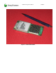
Figure 1: DM-15/25 Module.....................................................................................................................8
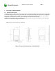
Figure 3: 30-pin system connector ..........................................................................................................11
Figure 4: 30-pin system connector footprint............................................................................................12
Figure 5 PCM timing diagram for DM-15/DM-25 ..................................................................................19
Revision History
RELEASE DATE SUMMARY OF CHANGES
A 2/14/02 Initial Release- MCH
P1B 2/27/02 Added FCC warning in 4.3.3
P2B 4/02/02 Removed Developer’s Kit and AT Commands.
Added FCC and Safety section. Added I/O Description