Contents 1 Introduction 4 2 Main Features 6 3 Operation 7 3.1 Signal Processing Overview . . . . . . . . . . . . . . . . . . . . . . . . . . . . 7 3.2 Resolution, Kernel Sizes, and Delays . . . . . . . . . . . . . . . . . . . . . . . 9 3.2.1 Delay Compensation and Audio Buffer Sizes . . . . . . . . . . . . . . 11 3.2.2 Over-Taxing the Host . . . . . . . . . . . . . . . . . . . . . . . . . . . 12 3.3 Advanced Operation . . . . . . . . . . . . . . . . . . . . . . . . . . . . . . . . 13 3.3.
10 Copyright and Acknowledgements 41
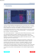
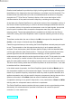
1 1 INTRODUCTION Introduction The Sonnox Oxford SuprEsser was designed primarily to be the last word in ‘de-essing’ applications. While we worked on creating the best possible de-essed sound, we found that we needed more control than was available on conventional De-Essers. Most de-essing work can be carried out in ‘simple’ mode but sometimes, to do the job properly, it is necessary to utilise all the controls of the underlying engine — a full-blown dynamic EQ, or frequency- conscious compressor.
1 INTRODUCTION Detailed visual feedback is provided by a highly intuitive graphical display, allowing quick identification of the frequencies that need treatment, and where to set the threshold. The threshold level and peak-hold level of the user-definable band are shown on the graph, alongside the FFT (Fast Fourier Transform) display of the narrow band signal, which includes retention of the peak level and the frequency containing the most energy.
2 2 MAIN FEATURES Main Features • Highly featured professional De-Esser • Linear-phase Dynamic EQ • Transparently controls aggressive frequencies • Automatic level-tracking follows energy level (eliminating the need to automate threshold) • Large intuitive graphic display makes finding frequencies very easy • Full spectrum operation (20Hz–20kHz) • Three different ‘Listen’ modes • Very easy to use • Advanced mode for ultimate control of the Dynamic EQ • Many creative as well as corrective uses • Presets pro
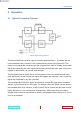
3 3 3.1 OPERATION Operation Signal Processing Overview Basic SuprEsser signal flow The Oxford SuprEsser contains a pair of mutually opposing filters — by default one is a narrow bandpass filter, the other is the complementary narrow band-reject filter. This results in one signal path containing just the contents of the band of interest, and another signal path containing the input signal with this band entirely removed; when mixed back together in equal ratios, you get the original signal.
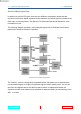
3.1 Signal Processing Overview 3 OPERATION Advanced Mode Signal Flow In addition to the four EQ types, there are four different compressor modes that are concerned with which signal is passed to the sidechain and which signal is passed to the main input of the compressor. See Section 2.3 Advanced Operational Modes for more information on this.
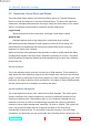
3.2 3.2 Resolution, Kernel Sizes, and Delays 3 OPERATION Resolution, Kernel Sizes, and Delays The linear-phase filters used by the Oxford SuprEsser require an ‘Impulse Response Kernel’ to model the response of the internal Oxford Filters. The size of this kernel (as measured in samples) determines both the plug-in delay and the accuracy of the model, which in turn affects the performance, especially at lower frequencies.
3.2 Resolution, Kernel Sizes, and Delays 3 OPERATION region of 4116 to 12308 samples. See the section below for information on reducing the delay. Oxford SuprEsser LL/LowLatency This small kernel version has a kernel size of 512 samples.
3.2 Resolution, Kernel Sizes, and Delays 3.2.1 3 OPERATION Delay Compensation and Audio Buffer Sizes The plug-in delay produced by the Oxford SuprEsser depends both on the kernel size/resolution and the audio block size. The block size is the size of the sample buffers passed to the plug-in by the host, and is usually specified in your audio hardware preferences/configuration/setup page.
3.2 Resolution, Kernel Sizes, and Delays 3.2.2 3 OPERATION Over-Taxing the Host The Oxford SuprEsser uses a process called convolution to implement filtering, a process that is expensive on CPU resources. When using very large kernel sizes, in combination with small audio buffer sizes, it is possible for the plug-in to take longer than an entire audio block to complete processing, with the result that (from a monitoring point of view) the playback breaks up.
3.3 Advanced Operation 3.3 3 OPERATION Advanced Operation 3.3.1 Trigger and Gain-Ducking Modes There are four major operational modes selectable via the TRIGGER and AUDIO buttons in the Advanced Mode (MORE:) section, as described below: Mode: Signal to: Trigger Audio Comp Side Chain Band Filtered Filtered signal signal Band Result Gain ducking occurs only in the narrow band, triggered by the narrow band.
3.3 Advanced Operation 3 OPERATION Band-Band Mode In this mode (the default) both the trigger signal (to the compressor sidechain) and the main compressor signal is the narrow-bandpass-filtered signal. The output of the compressor is then fed to the crossover block (the ‘Listen’ section) for mixing back in with the version of the input signal that has been filtered with the corresponding narrow-band-reject filter.
3.3 Advanced Operation 3 OPERATION In this mode, when you also use the Auto Level Track function (AUTO IN), the threshold follows the general level of the signal post the narrow-band-reject-filter, (ie. everything except the troublesome frequencies). Furthermore, the crossover controls (in the LISTEN section) have no effect on the signal because the output of the compressor is already a complete wide-spectrum signal.
3.3 Advanced Operation 3 OPERATION into the compressed signal. This can be used to create that unique sound in which a fully compressed signal (with no dynamic headroom) has some punch added back into it. In this mode, the LISTEN section has no effect on the signal because the output of the compressor is already a complete wide-spectrum signal. 3.3.2 Automatic Level Tracking Auto Level Tracking mode is enabled by selecting the LEVEL TRACKING/AUTO IN button. This is ON by default.
3.3 Advanced Operation 3 OPERATION Auto Level Tracking therefore works well with continuous material, or with conversation broken up with frequent pauses. Setting the After-Silence Start Level If the above algorithm is tending to under-correct when the vocalist starts singing after a pause, you can, if you wish, set the ‘After-Silence Start Level’ by moving the threshold fader while the plug-in is receiving silence or is non-active.
3.3 Advanced Operation 3.3.3 3 OPERATION Bandpass Filter Modes Bandpass Mode By default, the Oxford SuprEsser uses a bandpass filter (along with its inverse filter, the band-reject filter) to isolate the audio in the frequency range selected. The FREQUENCY and WIDTH controls defines the low and high edges of the filters used, and the SLOPE/Q control defines how quickly a signal blends from gain-ducked to non-gain-ducked in the frequency spectrum.
4 DESCRIPTION OF CONTROLS you activate HF-Cut Filter mode. This means that the upper edge of the bandpass window is effectively at infinity Hz, and this is useful, for example, when you want to duck the entire HF part of the signal. In this mode you can think of operation as an HF-Cut Filter that activates only when the signal reaches a certain threshold, in which the cut-off frequency is defined by the lower edge of the bandpass window. This is how some more primitive De-Essers work. 4 4.
4.1 Basic Screen Controls 4.1.1 4 DESCRIPTION OF CONTROLS Touch Pad Controls Many of the controls on the Oxford SuprEsser are implemented using ‘Touch Pads’.
4.1 Basic Screen Controls 4.1.2 4 DESCRIPTION OF CONTROLS Options Menu Clicking the Sonnox button produces a drop-down options menu: Clip Lights These options determine the approximate time that an overload indicator will stay on for when the plug-in has detected a full-level sample at either its input or output. Enable Sonnox Toolbar Displays or hides the Sonnox Preset Manager Toolbar (see Section 4).
4.1 Basic Screen Controls 4.1.3 4 DESCRIPTION OF CONTROLS Input Monitor Section Input Level Meter This meter is designed to give exactly 1dB per LED for the top 18dB of dynamic range, and 2dB per LED thereafter. This gives a clear and intuitive impression of the working headroom. Level Trim dB Touch Pad This allows you to adjust the input signal level by up to +/- 12dB.
4.1 Basic Screen Controls 4 DESCRIPTION OF CONTROLS OUTSIDE Button This sets the crossfade so that you are listening only to the output of the band-reject filter — which is everything outside of the bandpass window, hence the name. In this mode, if you sweep the centre frequency of the band filter up and down the spectrum, the troublesome noises will disappear when you have hit the area to work on. 4.1.
4.1 Basic Screen Controls 4 DESCRIPTION OF CONTROLS filters. Generally speaking, you want the highest setting for maximum separation between troublesome and non-troublesome sounds. However, you may find musical or creative possibilities in using gentler slopes. For example, when using lower settings there is a smoother blend between gain-ducked components and the original, which will be more noticeable when using large amounts of gain reduction.
4.1 Basic Screen Controls 4 DESCRIPTION OF CONTROLS ATTENUATION Meter This meter gives an indication of how much gain reduction is occurring, both instantaneously, and with a peak-hold level that indicates the maximum reduction in the previous couple of seconds. The meter operates in increments of exactly one dB. MORE: ACCESS Button When you need to access the complete set of dynamics controls, click on the ACCESS button to open up the ‘advanced’ control set.
4.1 Basic Screen Controls 4.1.7 4 DESCRIPTION OF CONTROLS OUTPUT MONITOR Section TRIM dB Touch Pad This allows you to reduce the output level by up to 12dB. Dithering is applied after the output gain control, so it may be necessary to reduce this value by a small amount to avoid clipping. WET/DRY Touch Pad This control enables you, if you want, to mix in some of the original input with the output, rather like the Wet/Dry control on a reverb.
4.2 4.2 Advanced Screen Controls 4 DESCRIPTION OF CONTROLS Advanced Screen Controls The advanced screen, and its associated controls, is provided to allow the Oxford SuprEsser to be used as a general-purpose frequency-specific compressor, giving you access to all the controls within the plug-in’s dynamics section. MODE Section TRIGGER Button This toggles between Wide and Band, and controls the type of signal fed to the sidechain of the compressor, ie.
4.2 Advanced Screen Controls 4 DESCRIPTION OF CONTROLS LEVEL TRACKING Section AUTO IN Button This controls the mode of the threshold functionality. In ‘Auto-Level- Tracking’ mode (ie. with the IN button selected), the compressor’s trigger threshold follows the general level of the wide input signal, and the THRESHOLD fader adjusts the threshold relative to that general signal level.
4.2 Advanced Screen Controls 4 DESCRIPTION OF CONTROLS REACTION ENVELOPE Section The ATTACK, HOLD and RELEASE controls together define the shape of the gain reduction envelope created when a transient breaches the threshold. ATTACK Touch Pad This defines how quickly the gain reduction can kick in. While fast attack times often seem to be the best idea, slower attack times can sound more musical and natural. In general, for de-essing, fast attack times are required — as fast as possible without distortion.
4.2 Advanced Screen Controls 4 DESCRIPTION OF CONTROLS RATIO Section RATIO Fader and Touch Pad This defines the input to output gain ratio of the compressor, once the signal has reached the level of the threshold value.
4.2 Advanced Screen Controls 4 DESCRIPTION OF CONTROLS SOFT KNEE Button This control allows for a gradual onset of gain reduction as the signal level approaches the threshold level, rather than a sudden onset of gain reduction when the signal level actually hits the threshold. The larger the value set here (in 5dB steps up to 20dB), the earlier the onset of gain reduction prior to reaching the threshold.
4.3 4.3 Graphical Screen Controls 4 DESCRIPTION OF CONTROLS Graphical Screen Controls Lower Drag Handle (5) Peak Level (3) Threshold Line (1) Centre Drag Handle (4) Gain Reduction (2) Upper Drag Handle (6) . Zoom (9) Input Signal (8) Peak Frequency (10) Inside Band Signal (7) The Oxford SuprEsser’s graphical display is the key to its intuitive operation.
4.3 Graphical Screen Controls 4 DESCRIPTION OF CONTROLS To help you find the threshold, the most important place to look is the red time-domain peak reading (3). This gives the peak dB level of the audio signal leaving the bandpass filter. Below this, you will see a blue line representing the threshold (1). The distance between these two lines indicates the amount of gain reduction of peaks that you will achieve.
4.3 Graphical Screen Controls 4 DESCRIPTION OF CONTROLS out, for example, what consonants they represent. Gain Reduction Indicator This red-note area gives a real-time indication of the shape and amount of occurring gain reduction. The shape follows the slope indicators, and roughly corresponds to the shape of the pink FFT region (see 7 above). Threshold Line This line shows the current threshold level.
5 5 OXFORD SUPRESSER DS (AAX DSP) Oxford SuprEsser DS (AAX DSP) The Oxford SuprEsser DS is a highly-featured professional De-Esser AAX DSP plug-in for use with Avid S3L live consoles and Pro Tools|HDX. In order to provide high-quality processing with low latency, the kernel size has been reduced to 128 samples and the GUI focusses on frequencies greater than 1 kHz. This enables highly effective deessing with less than 2 ms of delay at 48 kHz. The SuprEsser DS includes AAX DSP and AAX Native components.
6 6 SPECIFICATIONS Specifications Supported Sample Rates Native (LL, Normal, HR) 22.05 to 44.1 kHz [1] Native (LL, Normal, HR) 44.1, 48, 88.2, 96, 176.4, 192 kHz AAX DSP (SuprEsser DS) 44.1 and 48 kHz Note: [1] At sample rates below 44.1 kHz the internal dynamics algorithm still uses 20 samples of look-ahead. So for samples rates lower than 44.1kHz, you may need to reduce your attack and release times in order for the processing to sound as expected. www.sonnox.
6 Input-Output Parameters Input Trim -12 to 12 dB Output Trim 0 to -12 dB Wet/Dry 0 to 100 % SPECIFICATIONS Filters Width (LL, Normal, HR) 0.2 to 10 octaves Width (SuprEsser DS) 0.2 to 4.45 octaves Slope 12 to 72 dB/octave Frequency (LL, Normal, HR) 20 Hz to 20 kHz Frequency (SuprEsser DS) 1 kHz to 20 kHz Compressor Threshold 0 to -84 dBFS Attack 0.01 to 52 ms Hold 0.01 to 30 seconds Release 0.01 to 3.11 seconds Ratio (degrees) 45 to 0 to -22.5 Ratio 1:1 to Inf:1 to -2.
6.1 SuprEsser DS – Pro Tools | HDX & S3L – Instances per chip 6.1 6 SPECIFICATIONS SuprEsser DS – Pro Tools | HDX & S3L – Instances per chip 48 kHz 96 kHz 192 kHz Mono 3 1 – Stereo 2 1 – www.sonnox.
7 7 PRESET MANAGER TOOLBAR Preset Manager Toolbar The Oxford SuprEsser plug-in comes equipped with its own onboard Preset Manager, which is displayed as a toolbar at the top of the plug-in window, just as if the host created it (see above). The reasoning behind this is to allow increased portability of your presets across all the host applications, while also providing a consistent and versatile interface.
9 8 SYSTEM REQUIREMENTS Supported Platforms • Avid Pro Tools (AAX Native and DSP 32/64-bit) • VST hosts (32/64-bit) • AU hosts (32/64-bit) • Mac Intel OSX 10.6 or higher • Windows 7 and 8 (32/64-bit) 9 System Requirements For latest System requirements, please visit www.sonnox.com. All versions • Free iLok account • Appropriate product licence • iLok2 Pro Tools • Approved Digidesign/Avid CPU and hardware configuration • Pro Tools 10.3.
10 10 COPYRIGHT AND ACKNOWLEDGEMENTS Copyright and Acknowledgements Trademarks and content copyright © 2007-present Sonnox® Ltd. All rights reserved. Sonnox® and the five dots logo are registered trademarks of Sonnox Ltd. This product is manufactured and supplied by Sonnox Ltd. This product is protected by one or more European and/or US patents. DIGIDESIGN, AVID and PRO TOOLS are trademarks or registered trademarks of Avid Technology Inc. VST is a trademark of Steinberg AG.