FUSION QR ™ 4-Drive Hardware RAID 5 SATA Disk Enclosure with Quad Interface User’s Guide For Windows
Contents 1 Fusion QR Features 1 2 Drive Installation and Enclosure Setup 2 Install Drives Connect the Fusion QR to Computer and Power Outlet 3 Drive Mode Descriptions 5 4 Drive Mode Configuration Instructions 7 Initial Drive Mode Configuration Change Drive Mode 5 Drive Formatting Instructions 8 OS X Users’ Instructions Windows Users’ Instructions 6 Status LED Indications 9 System Powered, No Drive Activity Drive Activity Drive Not Recognized RAID 5 or RA
1 – Fusion QR Features ❶❷❷ ❷❸ ❻ ❻ 1–P ower Indicator This blue LED lights when the Fusion QR is powered. ❹ ❺ ❻ 2–P resence, Activity, and Fault Indicators — Drives A – C These LEDs indicate the ready state (solid green), read and write activity (flashes green), and fault status (OFF or red) for drives A – C. An LED will remain off if the corresponding drive is not recognized, and will turn red if the drive is recognized but can’t be used.
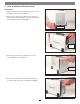
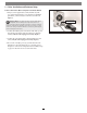
2 – Drive Installation and Enclosure Setup Install Drives 1. Remove the Fusion QR from its packaging, and place it on a flat, level surface, with the front panel facing you. 2. Lift up the front of the enclosure, slide the inner chassis lock switch to the left and hold it (Figure 1), and then push the inner chassis from the back until it stops (Figure 2). slide lock switch to left, and hold it Figure 1 push the inner chassis in until it stops Figure 2 3.
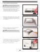
2 – Drive Installation and Enclosure Setup WARNING: When handling computer products, take care to prevent components from being damaged by static electricity; avoid working in carpeted areas. Handle hard drives only by their edges and avoid touching circuit boards and connector pins. 5. Remove a drive from its packaging and set it in on a flat, level surface with the label side up.
2 – Drive Installation and Enclosure Setup Connect the Fusion QR to Computer and Power Outlet 1. Using one of the supplied cables (eSATA, FireWire 800, USB 3.0), connect the Fusion QR to your computer. For maximum performance, connect the QR to a SATA host controller card (Figure 9).
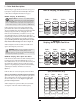
3 – Drive Mode Descriptions The following two pages describe the drive modes supported by the QR. To configure the Fusion DE400‑QR’s drives, refer to Drive Mode Configuration Instructions on page 7. RAID 0: Striping, No Redundancy RAID 0: Striping, No Redundancy Support Note: In all modes except JBOD, Sonnet strongly recommends you use four identical drives in the Fusion QR.
3 – Drive Mode Descriptions RAID 5: Striping, Parity Distributed Among Drives RAID 5 configuration increases reliability while using fewer drives than RAID 10 mirroring by using parity redundancy: parity is distributed across multiple drives. Any one of the four drives can fail, and the volume will continue to function. See Figure 13. When the failed drive is replaced, the parity data on the three other drives is used to rebuild the RAID volume with data spread across all four drives.
4 – Drive Mode Configuration Instructions Initial Drive Mode Configuration Configure as RAID 0 Volume ❷ press and hold, and then turn on the power WARNING: Configuring the drives in your Fusion 23 ❸ LEDs stay off ❶ turn to 0 4 0 1 When you first turn on the Fusion QR after installing the hard drives, you must select a mode to configure the drives before using your operating system to format them and make them ready for use.
5 – Drive Formatting Instructions OS X Users’ Instructions Windows 8/7/Vista and Server 2012/2008 Users’ Instructions 1. After the Fusion QR finishes configuring the drives, a Disk Insertion window will appear stating that there is an unreadable volume; click Initialize, and then Disk Utility will open. Note that if you configured the drives as JBOD, multiple Disk Insertion windows will open; clicking Initialize on the first window will cause Disk Utility to launch. 1.
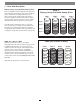
6 – Status LED Indications System Powered, No Drive Activity System Powered, No Drive Activity When the Fusion QR is powered on, and no data is being written to or read from the drives, the Power and Drive LEDs stay on (Figure 20). LEDs stay on Figure 20 Drive Activity (Data Reads and Writes) Drive Activity When data is being read from or written to a drive, its corresponding LED will flash (Figure 21).
7 – Specifications, Warnings, and Additional Information Specifications External Connectors USB 3.