
Installation Sheet

June 10, 2019
©2019 SONNEMAN - A WAY OF LIGHT
25 of 26
Power Feed Installation
Assembly Instructions
INSTRUCTIONS D’INSTALLATION
Important
• Always disconnect the power before installing or replacing components and before cleaning or other main-
tenance.
• Consult a qualied, licensed electrician to ensure correct branch circuit conductor.
Consulter un électricien qualifié pour vous assurer que les conducteurs de la dérivation sont adéquats.
Note
• This fixture is dimmable with Electronic Low Voltage (i.e., Trailing-Edge/Reverse Phase) type dimmers ONLY.
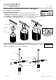
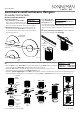
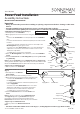
Ceiling Mount Standard Power Feed (Fig. 1):
1. Shut off power to the Outlet Box.
2. Make appropriate electrical connections using wire
nuts:
a. Connect the Transformer's live wire (black) to the live Outlet Box
wire.
b. Connect the Transformer's neutral wire (white) to the neutral outlet
box wire.
c. Connect the ground outlet box wire (green or uncoated) to the
Mounting Plate using the green screw.
d. Connect one of the Power Feed wires to one of the Transformer
output wires. Connect the other Power Feed wire to the second
Transformer output wire.
e. Carefully place connections in Outlet Box.
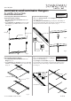
3. Attach the Mounting Plate to the outlet box, secure with Outlet Box
Screws.
4. Install the Power Feed to the Mounting Plate by fastening Set Screws
using Allen Key.
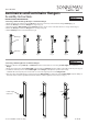
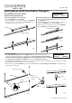
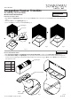
Note: To attach a Power Bar, remove Flat Head Screw and Support Cap
and align Power Bar with support. Press rmly on the bottom of the Power
Bar into the Power Feed, until the Power Bar clicks into place. Reattach
Support Cap with Flat Head Screw.
5. Restore power to the Outlet Box.
Outlet box
Transformer
Mounting
Plate
Outlet
Box
Screw
Set
Screws
Allen
Key
Power
Feed
Flat Head
Screws
Fig. 1
Fig. 2
Support
Cap
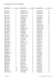
1XA08CE01K
Applies to Components:
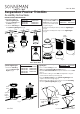
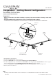
Ceiling Mount Remote Power Feed
(Fig. 2):
1. Shut off power to the Remote
Power Supply.
2. Drill hole a for wires at the mounting location.
3. Make appropriate electrical connections using wire nuts:
a. Connect the Transformer's live wire (black) to the
live Supply Wire.
b. Connect the Transformer's neutral wire (white) to the
neutral Supply Wire.
d. Connect one of the Power Feed wires to one of the
Transformer output wires. Connect the other Power
Feed wire to the second Transformer output wire.
e. Carefully place connections into wall.
4. Install the Power Feed to the wall with Anchor and
Screw
Note: To attach a power bar, remove Flat Head Screw
and Support Cap and align Power Bar with support.
Press rmly on the bottom of the Power Bar into the
Power Feed, until the Power Bar clicks into place. Reattach
Support Cap with Flat Head Screw.
5. Restore power to the Remote Power Feed.
Flat Head Screws
Support Cap
Anchor
Screw
Power Feed
Transformer
Supply Wires
1XA08CE02K
Applies to Components: