
Installation Sheet

June 10, 2019
©2019 SONNEMAN - A WAY OF LIGHT
22 of 26
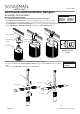
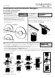
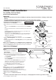
Connecting a Trim to a Cylinder
Light Engine:
1. Place a rubber O-Ring on each
Arm on the Parachute Reflector Rrim (Fig. 2).
2. Bend the Parachute Reflector and pass each hole over an Arm
(Fig. 3).
3. Place another O-Ring on each Arm and adjust the o-rings to
set the desired reector position (Fig. 4).
4. Place the Reflector Ring on the Cylinder Light Engine and
adjust to the desired angle (Fig. 5).
5. While holding the reector ring in place, screw the Trim Ring
into the Cylinder Light Engine (Fig. 6).
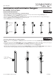
Connecting a Trim to a
Cylinder Light Engine:
1. Screw the Trim Ring
into the Cylinder Light
Engine (Fig. 1).
Fig. 5
Fig. 6
Parachute
Reflector
O-Ring
Trim Ring
Reflector
Ring
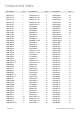
1XZ010004x 1XZ010005x
Applies to Components:
1XZ010001x
1XZ010002x
1XZ010003x
1XZ010015x
1XZ010016x
1XZ010017x
1XZ010018x
1XZ010019x
1XZ0201xxx
Applies to Components:
Fig. 1
Trim
Ring
Cylinder
Light
Engine
Arm
Suspenders Precise
TM
Trim Kits
Assembly Instructions
INSTRUCTIONS D’INSTALLATION
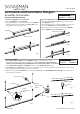
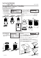
Connecting a Trim to a
Cylinder Light Engine:
1. Insert the Trim Ring into
the Shade. (Fig. 1)
2. Screw the Trim Ring into
the Cylinder Light Engine. (Fig. 2)
Fig. 1
Fig. 2
1XZ010010x
1XZ010011x
1XZ010012x
1XZ010013x
1XZ020701x
1XZ020801x
Applies to Components:
Trim
Ring
Applies to
Glass Shade Trims
Shade
Cylinder
Light
Engine
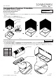
Fig. 2
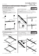
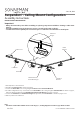
Power Precise Round Trims:
1. Align the Lens, Shade, and
Bezel with each other (Fig.
3) then preassemble them
together (Fig. 4).
2. Align the assembly from step 1 with the Light Engine
(Fig. 5).
3. Screw the assembly from step 1 to the Light Engine
(Fig. 5).
Fig. 3
Fig. 4
Fig. 3
Lens
Shade
Bezel
Light
Engine
Applies to Components:
1XZ0202xxx
1XZ0203xxx
1XZ0205xxx
1XZ0206xxx