
Installation Sheet

March 09, 2016
©2016 SONNEMAN - A Way of Light
21 of 29
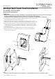
Minibox Wall Sconce Power Feed Installation
Assembly Instructions
INSTRUCTIONS D’INSTALLATION
Important
• Always disconnect the power before installing or replacing bulbs and before cleaning or other maintenance.
• Consult a qualied, licensed electrician to ensure correct branch circuit conductor.
Consulter un électricien qualié pour vous assurer que les conducteurs de la dérivation sont adéquats.
A
B
C
E
F
D
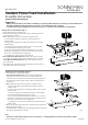
1. For remote transformer use: The transformer must be
installed in an accessible location in accordance with local
electrical codes. You must use the appropriate wire gauge from
the transformer to the Power Feed to limit the voltage drop to
less than 5%.
2. Shut o power to the branch circuit conductor.
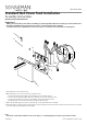
3. Cut an opening in the mounting surface (minimum 3/8" thick)
that measures 1.5" wide by 2.75" high. (Fig. 1)
4. Pull 1/2 trade size exible metal conduit or building cable (A)
through the opening. (Fig. 1)
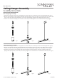
5. Remove the three Phillips screws (B) and separate the Minibox
into upper (C) and lower (D) halves. (Fig. 1)
6. Remove the knockout tab from the upper half (C) and
attach the cable/conduit (A) to the knockout opening using
appropriate connectors (Note: Cable/conduit and connectors
not included). (Fig. 1)
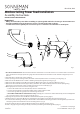
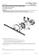
7. Make appropriate electrical connections using wire nuts:
a. Connect the transformer's live wire (black) to the live outlet
box wire.
b. Connect the transformer's neutral wire (white) to the
neutral outlet box wire.
c. Connect the ground wire (green) to the outlet box ground
screw.
d. For 60W and 75W unhoused transformers only: Carefully
place connections and transformer (E) in lower half (D), with
the connections in the section near the knockout. (Fig. 1)
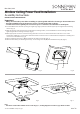
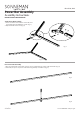
8. Flip wing tabs (F) inward so that the Minibox will t into the
drywall opening. (Fig. 2)
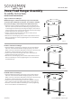
9. Reattach upper (C) and lower (D) halves by installing the three
Phillips screws (B) removed previously. (Fig. 1)
10. Loosen the two mounting screws (G) on the front face of the
Minibox until the gap between the wing tabs (F) and the side
tabs (H) is greater than the thickness of the mounting surface.
(Fig. 1)
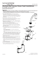
11. Flip wing tabs (F) inward so that the Minibox will t into the
drywall opening. (Fig. 2)
12. Slide O-rings (I) along mounting screws (G) so that they are
ush against the wing tabs (F). (Fig. 2)
G
H
(continued on next page)
Fig. 1
Fig. 2
I