
Installation Sheet

March 09, 2016
©2016 SONNEMAN - A Way of Light
17 of 29
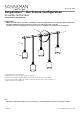
Linear, Tri-Bar, and Ring Power Feed Installation
Assembly Instructions
INSTRUCTIONS D’INSTALLATION
Important
• Always disconnect the power before installing or replacing bulbs and before cleaning or other maintenance.
• Consult a qualied, licensed electrician to ensure correct branch circuit conductor.
Consulter un électricien qualié pour vous assurer que les conducteurs de la dérivation sont adéquats.
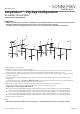
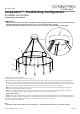
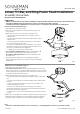
Deep Power Feed Installation (Fig. 1):
1. Shut o power to the outlet box (A).
2. Attach the crossbar (B) to the outlet box (A) using the two (2)
long screws (C).
3. Make appropriate electrical connections using wire nuts:
a. Connect the transformer's (D) live wire (black) to the live
outlet box wire.
b. Connect the transformer's neutral wire (white) to the neutral
outlet box wire.
c. Connect the ground outlet box wire (green or uncoated) to
the crossbar using the green screw.
d. Connect one of the black Power Feed (E) wires to one of the
transformer output wires. Connect the other black Power Feed
wire to the second transformer output wire.
e. Carefully place connections in outlet box (A).
4. For 150W and 300W transformers: Attach the transformer (D)
to the Power Feed (E) using the two (2) small screws (F).
For 60W and 75W transformers: Place the transformer inside
the Power Feed.
5. Install the Power Feed (E) to the crossbar (B) by passing the
nipple (G) through the hole in the Power Feed and securing with
the nial (H).
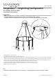
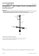
Shallow Power Feed Installation (Fig. 2):
1. Shut o power to the outlet box (A).
2. For remote transformer use: The transformer (D) must be installed in
an accessible location in accordance with local electrical codes. You must
use the appropriate wire gauge from the transformer to the Power Feed
to limit the voltage drop to less than 5%.
3. Make appropriate electrical connections using wire nuts:
a. Connect the transformer's (D) live wire (black) to the live outlet box
wire.
b. Connect the transformer's neutral wire (white) to the neutral outlet
box wire.
c. Connect the ground outlet box wire (green or uncoated) to the
crossbar using the green screw.
d. Connect one of the black Power Feed (E) wires to one of the
transformer output wires. Connect the other black Power Feed wire to
the second transformer output wire.
e. Carefully place connections and transformer (if applicable) in outlet
box (A)
4. Attach the crossbar (B) to the outlet box using the two (2) long screws (C).
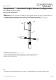
5. Install the Power Feed (E) to the crossbar (B) by passing the nipple (G)
through the hole in the Power Feed and securing with the nial (H).
Fig. 1
A
A
B
B
G
H
G
C
C
F
D
D
E
E
H
Fig. 2
Note
• This fixture is dimmable with Electronic Low Voltage (i.e., Trailing-Edge/Reverse Phase) type dimmers ONLY.