
Installation Sheet

B
D
F
E
C
K
H
A
J
G
L
Fig. 1
Fig. 2
P
O
B
©2019 SONNEMAN - A WAY OF LIGHT
2 of 3
December 20, 2019
Assembly Instructions
INSTRUCTIONS D’INSTALLATION
Papillons Series- 4-Light LED Pendant and 4-Light Large LED Pendant
Important
• Always disconnect the power before installing or replacing bulbs and before cleaning or other maintenance.
• Consult a qualied, licensed electrician to ensure correct branch circuit conductor.
Consulter un électricien qualié pour vous assurer que les conducteurs de la dérivation sont adéquats.
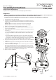
1. Shut o power to the outlet box (A).
2. Feed the power cords (B) through the bushings (C) and adjust to desired
height. Use included screwdriver (O) to tighten set screws (P) in bushing to
secure cords.
For 2902: Make sure collar (L) is about 8/" above the spreader (D).
For 2904: Make sure collar (L) is about 15" above the spreader (D).
3. Make sure spreader (D) is level by adjusting cord stops (E).
4. Reserve extra cord (B) in the canopy (F). If eld shortening of the cords is
necessary see Appendix A.
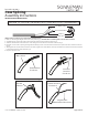
5. Make appropriate electrical connections using wire nuts and lever nuts, as
seen in Fig. 1:
a. Connect the LED driver’s (G) live wire (black) to the live outlet box wire.
b. Connect the LED driver’s (G) neutral wire (white) to the neutral outlet
box wire.
c. Connect the xture’s ground wire (green or uncoated) to the ground
outlet box wire. If no ground is present in outlet box, connect xture’s
ground wire to the mounting plate (H) using the green screw (included).
d. Carefully place connections and LED driver (G) in outlet box (A).
6. Attach the mounting plate (H) to the outlet box (A), secure with outlet box
screws (J).
7. Install the canopy (F) to the mounting plate and secure with Screws (K)
using the Screw Driver provided.
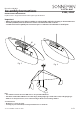
8. Install each shade by lowering the shade connector (L) over the cord collar
(M), sliding it forward until it stops, then tightening the shade screw (N)
(Fig. 3). If the shade connector can't move forward, rst loosen the screw
slightly. Fig. 4 shows assembled shade and Fig. 5 shows completed xture.
9. Adjust cord stops (E) again until the spreader (D) is level.
10. Restore power to the xture.
2902, 2904