Reference Monitor Controllers User Handbook RM-MC1L Monitor Controller, Single Stereo Input & Output With Light Control RM-MC4L Monitor Controller, 4 Stereo Inputs, 1 Output With Light Control RM-MC51L Monitor Controller, 5.
R EFERE NCE M ON ITOR CO NT ROLLERS USER H A N D BOOK REFERENCE MONITOR CONTROLLERS USER HANDBOOK b This handbook is for use with the following products. RM-MC1L Monitor Controller, Single Stereo Input & Output With Light Control RM-MC4L Monitor Controller, 4 Stereo Inputs, 1 Output With Light Control RM-MC51L Monitor Controller, 5.1 Stereo Inputs & Outputs With Light Control RM-MCL Monitor Light Controller, 3 Button, TX-STANDBY-REH ©Sonifex Ltd, 2010 All Rights Reserved Revision 1.
CONTENTS Warranty i i iii iii Safety Information iv Safety of Mains Operated Equipment Voltage Setting Checks Fuse Rating Power Cable and Connection Ordering the Correct Mains Lead iv iv iv iv v Installation Information v Atmosphere Electromagnetic Radiation WEEE & RoHS Directives - Sonifex Statement v v vi 1 Reference Monitor Controllers Introduction 1 2 RM-MC1L Monitor Controller 2 Front Panel Controls & Indicators Power LED Light Control Buttons DIM Button CUT Button Master Volume Control
FIGURES FI G U RE S Figures d Fig A: Packing List iii Fig B: Power Connections iv Fig C: Mains Lead Table v Fig 1-1: RM-MC1L Block Diagram 2 Fig 1-2: RM-MC1L Monitor Controller, Single Stereo Input & Output With Light Control 3 Fig 1-3: Rear View of RM-MC1L 5 Fig 2-1: RM-MC4L Block Diagram 7 Fig 2-2: RM-MC4L Monitor Controller, 4 Stereo Inputs, 1 Stereo Output With Light Control 8 Fig 2-3: Rear View of RM-MC4L 8 Fig 4-1: RM-MC51LBlock Diagram 9 Fig 4-2: RM-MC51L Monitor Controller, 5.
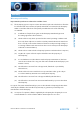
WARRANTY Warranty Warranty and Liability Important: the purchaser is advised to read this clause (a) The Company agrees to repair or (at its discretion) replace Goods which are found to be defective (fair wear and tear excepted) and which are returned to the Company within 12 months of the date of despatch provided that each of the following are satisfied: notification of any defect is given to the Company immediately upon its becoming apparent to the Purchaser; (ii) the Goods have only been operated un
WARRANTY WA RR A N T Y (c) ii The Company accepts liability: (i) for death or personal injury to the extent that it results from the negligence of the Company, its employees (whilst in the course of their employment) or its agents (in the course of the agency); (ii) for any breach by the Company of any statutory undertaking as to title, quiet possession and freedom from encumbrance.
WARRANTY Unpacking the Reference Monitor Controller The Reference Monitor Controller is shipped with the following equipment. Please check your packaging to ensure that you have all of the items below. If anything is missing, please contact the supplier of your equipment immediately.
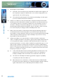
SAFETY INFORMATION Safety Information Safety of Mains Operated Equipment SAFE T Y IN FORMAT I ON This equipment has been designed to meet the safety regulations currently advised in the country of purchase and it conforms to the safety regulations specified by use of the CE Mark. Warning : There are no user serviceable parts inside the equipment. If you should ever need to look inside the unit, always disconnect the mains supply before removing the equipment covers.
SAFETY INFORMATION Ordering the Correct Mains Lead When ordering a Reference Monitor Controller from Sonifex, it is helpful if you can specify your required operating voltage and mains lead. After the product code add: UK, for 230V, UK 3 pin to IEC lead EC, for 230V, European Schuko 2 pin to IEC lead US, for 115V, 3 pin to IEC lead Fig C: Mains Lead Table E.g. order RM-MC1L UK for a UK IEC lead to be supplied.
WEEE & ROHS DIRECTIVE WEEE & RoHS Directives - Sonifex Statement WEEE & ROHS D I RE C T I VE The Waste Electrical and Electronic Equipment (WEEE) Directive was agreed on 13 February 2003, along with the related Directive 2002/95/EC on Restrictions of the use of certain Hazardous Substances in electrical and electronic equipment (RoHS).
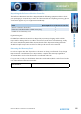
INTRODUCTION The Reference Monitor Controllers are a range of 1U rack-mount audio production control units, for providing source selection, volume, DIM and CUT controls for external analogue monitors, together with light controls for the Sonifex SignalLED range of studio signs, or similar. I N T ROD U C T ION 1 Reference Monitor Controllers Introduction Each of the products has a light control section. This section has 3 buttons: Transmit (TX), STANDBY and Rehearse (REH).
2 RM-MC1L Monitor Controller R M - M C 1 L M onitor Controller 2 RM-MC1L Monitor Controller The RM-MC1L is a stereo unit with a single stereo balanced analogue input and output. Useful in a production environment, the unit allows you to control the audio level to external monitors and to DIM the audio, or CUT it completely with simple front panel controls, or remote external inputs. It has a master volume control that adjusts the attenuation on the output channels from 0dB down to -86dB.
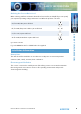
RM-MC1L Monitor Controller 2 Front Panel Controls & Indicators Light Control Buttons DIM CUT Button Button Power LED Fig 1-2: RM-MC1L Monitor Controller, Single Stereo Input & Output With Light Control Power LED The power LED illuminates blue whilst power is present within the unit. If this indicator is not on, the most likely reason is simply the absence of mains power, but under fault conditions it may also indicate a ruptured mains fuse or a problem with the internal power supply module.
2 RM-MC1L Monitor Controller If the Standby countdown is currently active, the countdown is cancelled and both the TX and Standby buttons are deactivated. DIM Button R M - M C 1 L M onitor Controller The DIM button attenuates the audio level at the output by a pre-set amount from -2dB to -23dB. The attenuation is applied after any level adjustment made by the master volume control. The DIM level is set by adjusting the DIM Level potentiometer on the rear panel.
RM-MC1L Monitor Controller 2 Rear Panel Controls & Connectors XLR Audio Inputs Mains Power Remotes DIM Level Potentiometer Fuse DIM Level Adjustment Potentiometer The DIM level potentiometer sets the attenuation applied to audio output when the DIM button is active. Turn the potentiometer clockwise to decrease the DIM attenuation level and clockwise to increase it (altering the audio level by -2dB to -23dB).
2 RM-MC1L Monitor Controller R M - M C 1 L M onitor Controller The GPIO port connector is a 15-way female D-type with the following pin assignments: 6 Pin Function Description 1 Digital Ground 0V 2 TX Output Collector Collector of optically-isolated driver for TX 3 REH Output Collector Collector of optically-isolated driver for REH 4 REH Output Tally Open collector driver active when REH is active 5 STANDBY Remote Input Active low input to trigger STANDBY 6 CUT Remote Input Active lo
RM-MC4L Monitor Controller 3 3 RM-MC4L Monitor Controller The RM-MC4L has four stereo balanced analogue inputs with a single stereo balanced output. The RM-MC4L has the same master volume control, CUT, DIM, light control functions, remote operation and adjustments as the RM-MC1L unit.
3 RM-MC4L Monitor Controller Front Panel Controls & Indicators R M - M C 4 L M onitor Controller Light Control Buttons Input Select Buttons DIM CUT Button Button Power LED Master Volume Control Fig 2-2: RM-MC4L Monitor Controller, 4 Stereo Inputs, 1 Stereo Output With Light Control Input Select Buttons The four input select buttons select which of the four stereo inputs is routed to the single stereo output.
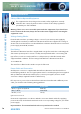
RM-MC51L Monitor Controller 4 4 RM-MC51L Monitor Controller The RM-MC51L is a monitor controller for surround sound applications with 6 balanced analogue inputs and 6 balanced analogue outputs. It is used in situations where you need to adjust the volume, or CUT, or DIM all of the speakers in a 5.1 surround system. Alternatively, the unit can be used as a global volume control for 6 analogue outputs.
4 RM-MC51L Monitor Controller Front Panel Controls & Indicators Light Control Buttons DIM CUT Button Button R M - M C 51 L M onitor Controller Power LED Master Volume Control Fig 4-2: RM-MC51L Monitor Controller, 5.1 Stereo Inputs & Outputs With Light Control For details of the RM-MC51L Monitor Controller front panel controls and indicators, please refer to the RM-MC1L description.
RM-MCL Monitor Controller 5 5 RM-MCL Monitor Controller The RM-MCL is a simple light controller for controlling a TX - STANDBY - REH light system in a production studio, as detailed in the RM-MC1L description. It has no audio inputs or outputs.
5 RM-MCL Monitor Controller Rear Panel Controls & Connectors Remotes Mains Power Fuse R M - M C L M onitor Controller Fig 5-3: Rear View of RM-MC1L 12 For details of the RM-MCL Monitor Controller rear panel connectors, please refer to the RM-MC1L description.
Technical Specification 6 6 Technical Specification Audio Specification >20kΩ Maximum Input Level: +25dBu Output Impedance: <50 Ω Maximum Output Level: +25dBu Attenuation Range: >86dB DIM Attenuation Range: Adjustable -3dB to -23dB via rear panel potentiometer Common Mode Rejection: >66dB typical Distortion: <0.
6 Technical Specification Power Consumption: RM-MC1L RM-MC4L RM-MC51L RM-MCL Peak 10W, average 4W Peak 10W, average 6W Peak 10W, average 7W Peak 10W, average 2W Fuse Rating: Anti-surge fuse 1A, 20 x 5mm T echnical S pecification Equipment Type 14 RM-MC1L: Monitor controller, single stereo input and output with light control RM-MC4L: Monitor controller, 4 stereo inputs, 1 stereo output with light control RM-MC51L: Monitor controller, 5.
NOTES N OT E S Reference Monitor Controllers User Handbook 15
N OT E S NOTES 16 Reference Monitor Controllers User Handbook
NOTES N OT E S Reference Monitor Controllers User Handbook 17
w w w. s o n i fe x . c o. u k t:+44 (0)1933 650 700 f:+44 (0)1933 650 726 s a l e s @ s o n i fe x . co.