
Manual
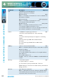
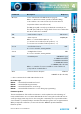
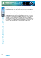
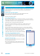
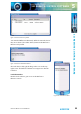
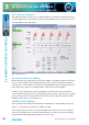

Table Of Contents
- Fig A: Packing List
- Fig B: Power Connections
- Fig C: Mains Lead Table
- Fig 1-1: RB-2S4 Reference Monitor Front Panel
- Fig 1-2: RB-2S10 Reference Monitor Front Panel
- Fig 1-3: Reference Monitor Block Diagram
- Fig 1-4: RM-2S4 Front Panel Controls
- Fig 1-5: RM-2S10 Front Panel Controls
- Fig 1-6: RM-2S4 Source Selector
- Fig 1-7: RM-2S10 Source Selector
- Fig 1-8: RM-2S4 & RM-2S10 Meters
- Fig 1-9: RM-2S4 & RM-2S10 DIPSwitch Settings
- Fig 1-10: Meter Labelling Options
- Fig 1-11: Brightness Control
- Fig 1-13: Balance Control
- Fig 1-12: Phase Meter Display
- Fig 1-14: Status LEDs
- Fig 1-15: RB-2S4 & RB-2S10 Modifier Switches
- Fig 1-16: Reference Monitor RM-2S4 Rear
- Fig 1-17: Reference Monitor RM-2S10 Rear
- Fig 1-18: RM-2S4 & RM-2S10 DIPswitch Settings
- Fig 2-1: RB-4C8 Reference Monitor Front Panel
- Fig 2-2: Reference Monitor Block Diagram
- Fig 2-3: RM-4C8 Front Panel Controls
- Fig 2-4: RM-4C8 Rotary Source Selectors
- Fig 2-5: RM-4C8 Meters
- Fig 2-6: RM-4C8 DIPSwitch Settings
- Fig 2-7: Meter Labelling Options
- Fig 2-8: Brightness Control
- Fig 2-9: Phase Meter Display
- Fig 2-10: Balance Control
- Fig 2-11: Status LEDs
- Fig 2-12: RB-4C8 Modifier Switches
- Fig 2-13: Reference Monitor RM-4C8 Rear
- Fig 3-1: RM-HD1 Expansion Card
- Fig 3-2: RM-HDE1 Expansion Card
- Fig 3-3: Reference Monitor RM-HD(E)1 Block Diagram
- Warranty
- Safety Information
- Installation Information
- Reference Monitors Introduction
- RM-2S4 Reference Monitor, 2 LED meters & 4 stereo
- channel inputs
- RM-2S10 Reference Monitor, 2 LED meters & 10 stereo
- channel inputs
- Technical Specification RM-2S4 & RM-2S10
- RB-4C8 Reference Monitor, 4 LED meters, 8 channel inputs &
- dual selectors
- Technical Specification RM-4C8
- RM-HD1 Reference Monitor HD-SDI Expansion Card &
- RM-HDE1 Reference Monitor HD-SDI & Dolby E Expansion Card
- Technical Specification RM-HD1 & RM-HDE1
- Serial Interface Commands & Responses Protocol

56
Reference Monitors User Handbook
SCI REMOTE CONTROL SOFTWARE
SCI REMOTE CONTROL SOFTWARE
5
SCi For Reference Monitors
The graphical interface allows you to control the Reference Monitor remotely. Bank/Source
Selection, EQ parameter adjustment and front panel Modier controls can all be accessed
and adjusted from this main panel.
Fig 5-5: SCi Main Screen
Bank & Source Selection & Editing
On the left hand side of this panel you have the ability to select Banks and their respected
Sources and to edit their names. Depending upon the model of your Reference Monitor,
or if expansion cards are tted, the number of available Banks varies. Each Bank shows its
respected Sources and you can edit the names of the Sources for each Bank.
To edit a Source or Bank name, click on the Edit icon located on the bottom left of the
screen and then click on the Source or Bank that you wish to edit. Type the Source or Bank
name into the text box and press ‘Enter’ on the keyboard. Press the Cancel button before
hitting the ‘Enter’ key to cancel the process.
5 Band Parametric Equalizer
The 5 band parametric EQ built into the Reference Monitors is only available using serial
control, so using SCi is an easy way to congure the EQ.
The 5 bands are shown on the screen and an ‘EQ Preset’ box allows you to select default
presets. The default presets cannot be edited. However you can generate preset settings
yourself, called Custom EQ Settings, which you can save o.