
Manual
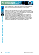
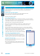
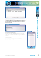
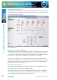
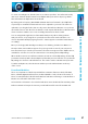

Table Of Contents
- Fig A: Packing List
- Fig B: Power Connections
- Fig C: Mains Lead Table
- Fig 1-1: RB-2S4 Reference Monitor Front Panel
- Fig 1-2: RB-2S10 Reference Monitor Front Panel
- Fig 1-3: Reference Monitor Block Diagram
- Fig 1-4: RM-2S4 Front Panel Controls
- Fig 1-5: RM-2S10 Front Panel Controls
- Fig 1-6: RM-2S4 Source Selector
- Fig 1-7: RM-2S10 Source Selector
- Fig 1-8: RM-2S4 & RM-2S10 Meters
- Fig 1-9: RM-2S4 & RM-2S10 DIPSwitch Settings
- Fig 1-10: Meter Labelling Options
- Fig 1-11: Brightness Control
- Fig 1-13: Balance Control
- Fig 1-12: Phase Meter Display
- Fig 1-14: Status LEDs
- Fig 1-15: RB-2S4 & RB-2S10 Modifier Switches
- Fig 1-16: Reference Monitor RM-2S4 Rear
- Fig 1-17: Reference Monitor RM-2S10 Rear
- Fig 1-18: RM-2S4 & RM-2S10 DIPswitch Settings
- Fig 2-1: RB-4C8 Reference Monitor Front Panel
- Fig 2-2: Reference Monitor Block Diagram
- Fig 2-3: RM-4C8 Front Panel Controls
- Fig 2-4: RM-4C8 Rotary Source Selectors
- Fig 2-5: RM-4C8 Meters
- Fig 2-6: RM-4C8 DIPSwitch Settings
- Fig 2-7: Meter Labelling Options
- Fig 2-8: Brightness Control
- Fig 2-9: Phase Meter Display
- Fig 2-10: Balance Control
- Fig 2-11: Status LEDs
- Fig 2-12: RB-4C8 Modifier Switches
- Fig 2-13: Reference Monitor RM-4C8 Rear
- Fig 3-1: RM-HD1 Expansion Card
- Fig 3-2: RM-HDE1 Expansion Card
- Fig 3-3: Reference Monitor RM-HD(E)1 Block Diagram
- Warranty
- Safety Information
- Installation Information
- Reference Monitors Introduction
- RM-2S4 Reference Monitor, 2 LED meters & 4 stereo
- channel inputs
- RM-2S10 Reference Monitor, 2 LED meters & 10 stereo
- channel inputs
- Technical Specification RM-2S4 & RM-2S10
- RB-4C8 Reference Monitor, 4 LED meters, 8 channel inputs &
- dual selectors
- Technical Specification RM-4C8
- RM-HD1 Reference Monitor HD-SDI Expansion Card &
- RM-HDE1 Reference Monitor HD-SDI & Dolby E Expansion Card
- Technical Specification RM-HD1 & RM-HDE1
- Serial Interface Commands & Responses Protocol

54
Reference Monitors User Handbook
SCI REMOTE CONTROL SOFTWARE
SCI REMOTE CONTROL SOFTWARE
5
Reference Monitor SCi Remote Control Software
Sonifex SCi software is free of charge software available to control the Reference Monitor
range of audio monitors, as well as other Sonifex products, using either RS232 or
USB connections.
Download the Latest SCi Software
This is located on the Sonifex website in the Software Downloads section:
http://www.sonifex.co.uk/technical/software/index.shtml
Download and install the software.
Connecting Using USB Port
Before the Reference Monitor can be used with the SCi software, you need to install the
latest version of the USB drivers. These can be found on the Sonifex website located in the
‘Sonifex Reference Monitor’ section of Software Downloads:
http://www.sonifex.co.uk/technical/software/index.shtml
Once you have downloaded the drivers, unzip them to a suitable folder. Connect
the Reference Monitor to your computer using a USB cable and power up the
Reference Monitor.
The ‘Found New Hardware’ wizard will pop up and you are ready to begin installation.
If Windows asks to connect to the internet to nd the drivers, select the option ‘Not this
Time’, click ‘Next’, and select the option ‘I Will Choose The Driver
To Install’. Point the wizard to the directory into which you
unzipped the USB driver les and continue with the installation.
Connecting using the RS232 Serial Port
You do not need to download drivers when connecting via
this method. Simply connect your Reference Monitor to your
computer using a serial cable and you are ready for operation.
Using SCi For The First Time
Once you are connected, double click the SCi icon. You will be
presented with the SCi Launcher:
Click on the large ‘Plus’ button and the software will try and
communicate with the relevant serial ports to ‘discover’ your
connected devices.
Fig 5-1: SCi Launcher