
Manual
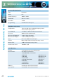
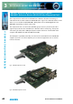
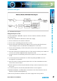
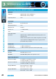
Table Of Contents
- Fig A: Packing List
- Fig B: Power Connections
- Fig C: Mains Lead Table
- Fig 1-1: RB-2S4 Reference Monitor Front Panel
- Fig 1-2: RB-2S10 Reference Monitor Front Panel
- Fig 1-3: Reference Monitor Block Diagram
- Fig 1-4: RM-2S4 Front Panel Controls
- Fig 1-5: RM-2S10 Front Panel Controls
- Fig 1-6: RM-2S4 Source Selector
- Fig 1-7: RM-2S10 Source Selector
- Fig 1-8: RM-2S4 & RM-2S10 Meters
- Fig 1-9: RM-2S4 & RM-2S10 DIPSwitch Settings
- Fig 1-10: Meter Labelling Options
- Fig 1-11: Brightness Control
- Fig 1-13: Balance Control
- Fig 1-12: Phase Meter Display
- Fig 1-14: Status LEDs
- Fig 1-15: RB-2S4 & RB-2S10 Modifier Switches
- Fig 1-16: Reference Monitor RM-2S4 Rear
- Fig 1-17: Reference Monitor RM-2S10 Rear
- Fig 1-18: RM-2S4 & RM-2S10 DIPswitch Settings
- Fig 2-1: RB-4C8 Reference Monitor Front Panel
- Fig 2-2: Reference Monitor Block Diagram
- Fig 2-3: RM-4C8 Front Panel Controls
- Fig 2-4: RM-4C8 Rotary Source Selectors
- Fig 2-5: RM-4C8 Meters
- Fig 2-6: RM-4C8 DIPSwitch Settings
- Fig 2-7: Meter Labelling Options
- Fig 2-8: Brightness Control
- Fig 2-9: Phase Meter Display
- Fig 2-10: Balance Control
- Fig 2-11: Status LEDs
- Fig 2-12: RB-4C8 Modifier Switches
- Fig 2-13: Reference Monitor RM-4C8 Rear
- Fig 3-1: RM-HD1 Expansion Card
- Fig 3-2: RM-HDE1 Expansion Card
- Fig 3-3: Reference Monitor RM-HD(E)1 Block Diagram
- Warranty
- Safety Information
- Installation Information
- Reference Monitors Introduction
- RM-2S4 Reference Monitor, 2 LED meters & 4 stereo
- channel inputs
- RM-2S10 Reference Monitor, 2 LED meters & 10 stereo
- channel inputs
- Technical Specification RM-2S4 & RM-2S10
- RB-4C8 Reference Monitor, 4 LED meters, 8 channel inputs &
- dual selectors
- Technical Specification RM-4C8
- RM-HD1 Reference Monitor HD-SDI Expansion Card &
- RM-HDE1 Reference Monitor HD-SDI & Dolby E Expansion Card
- Technical Specification RM-HD1 & RM-HDE1
- Serial Interface Commands & Responses Protocol

50
Reference Monitors User Handbook
SERIAL INTERFACE COMMANDS & RESPONSES
SERIAL INTERFACE
COMMANDS & RESPONSES
4
Command Description Response
LCK: - AES/EBU PLL Lock status Request
Response depends on model type:
RM-2S4 responds: LCK:x
Where: x = lock status of selected stereo source. No further lock
information is available.
RM-2S10 responds: LCK:x+yyyyyyyyyy
Where: x = lock status of selected stereo source.
y = lock status of all ten AES inputs.
RM-4C8 responds: LCK:xy+zzzz
Where: x = lock status of left selected mono source.
y = lock status of right selected mono source.
z = lock status of four mono sources in currently selected bank.
No lock data is available for an unselected bank.
LCK:ab - Set GPIO lock output logic preferences ACK:
a = 0 selects normal polarity (lock = low/conducting
output).
a = 1 selects inverted polarity (lock = high/non-conducting
output).
b = 0 selects the logical OR of the LH & RH channel
lock status.
b = 1 selects the logical AND of the LH & RH channel
lock status.
MOD:x,y - Remote control of audio Modiers ACK:
Where: x = modier number, 0 to A (hex - values B to F accepted
but have no eect).
y = 0 to turn modier o.
y = 1 to turn modier on (hex values 1 to F accepted and have
same eect as 1).
The modier numbers are:
0 = DIM, 1 = CUT L, 2 = CUT R, 5 = MONO, 6 = PHASE INVERT and
7 = M+S
OPT:x,yy - Set technical options ACK:
x = option number (1…F in hex)
yy = new value for option parameter (00…FF in hex)
All OPT settings are stored in non-volatile memory and retained
during power loss.
OPT:1,xx -Turn o presence detection: ACK:
Where: x = 00 enables the presence detectors (default setting).
x = 01 disables the presence detectors (hex values 01 to FF
accepted and have same eect as 01).