
Manual
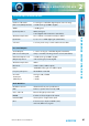
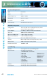
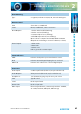
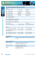
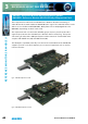
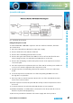
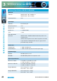
Table Of Contents
- Fig A: Packing List
- Fig B: Power Connections
- Fig C: Mains Lead Table
- Fig 1-1: RB-2S4 Reference Monitor Front Panel
- Fig 1-2: RB-2S10 Reference Monitor Front Panel
- Fig 1-3: Reference Monitor Block Diagram
- Fig 1-4: RM-2S4 Front Panel Controls
- Fig 1-5: RM-2S10 Front Panel Controls
- Fig 1-6: RM-2S4 Source Selector
- Fig 1-7: RM-2S10 Source Selector
- Fig 1-8: RM-2S4 & RM-2S10 Meters
- Fig 1-9: RM-2S4 & RM-2S10 DIPSwitch Settings
- Fig 1-10: Meter Labelling Options
- Fig 1-11: Brightness Control
- Fig 1-13: Balance Control
- Fig 1-12: Phase Meter Display
- Fig 1-14: Status LEDs
- Fig 1-15: RB-2S4 & RB-2S10 Modifier Switches
- Fig 1-16: Reference Monitor RM-2S4 Rear
- Fig 1-17: Reference Monitor RM-2S10 Rear
- Fig 1-18: RM-2S4 & RM-2S10 DIPswitch Settings
- Fig 2-1: RB-4C8 Reference Monitor Front Panel
- Fig 2-2: Reference Monitor Block Diagram
- Fig 2-3: RM-4C8 Front Panel Controls
- Fig 2-4: RM-4C8 Rotary Source Selectors
- Fig 2-5: RM-4C8 Meters
- Fig 2-6: RM-4C8 DIPSwitch Settings
- Fig 2-7: Meter Labelling Options
- Fig 2-8: Brightness Control
- Fig 2-9: Phase Meter Display
- Fig 2-10: Balance Control
- Fig 2-11: Status LEDs
- Fig 2-12: RB-4C8 Modifier Switches
- Fig 2-13: Reference Monitor RM-4C8 Rear
- Fig 3-1: RM-HD1 Expansion Card
- Fig 3-2: RM-HDE1 Expansion Card
- Fig 3-3: Reference Monitor RM-HD(E)1 Block Diagram
- Warranty
- Safety Information
- Installation Information
- Reference Monitors Introduction
- RM-2S4 Reference Monitor, 2 LED meters & 4 stereo
- channel inputs
- RM-2S10 Reference Monitor, 2 LED meters & 10 stereo
- channel inputs
- Technical Specification RM-2S4 & RM-2S10
- RB-4C8 Reference Monitor, 4 LED meters, 8 channel inputs &
- dual selectors
- Technical Specification RM-4C8
- RM-HD1 Reference Monitor HD-SDI Expansion Card &
- RM-HDE1 Reference Monitor HD-SDI & Dolby E Expansion Card
- Technical Specification RM-HD1 & RM-HDE1
- Serial Interface Commands & Responses Protocol

Reference Monitors User Handbook
49
REFERENCE MONITORS RM-4C8
2
Reference Monitors User Handbook
49
SERIAL INTERFACE
COMMANDS & RESPONSES
4
SERIAL INTERFACE COMMANDS & RESPONSES
Serial Interface Commands & Responses Protocol
Sonifex SCi remote control software handles all communication with the Reference
Monitors via a convenient graphical user interface. However, this protocol is provided for
those users who wish to develop their own remote control applications or communicate
with the Reference Monitors using a text-based terminal program.
For more information on how to install and operate the SCi software, please see page 54.
Serial Data Format
Connection is 19200,e,8,1 with XON/XOFF ow control.
Commands are case-insensitive and all parameters are in hex.
Commands should be terminated in a carriage return character, a line feed character may
be sent but it will be ignored.
Further commands sent before the rst command is acknowledged will be ignored.
Responses will be CR & LF terminated.
After power up a welcome string is sent – “Initialising Sonifex Reference Monitor…done”
Remote Control Commands
Command Description Response
BSL:nn - Select input Bank ACK:
nn = 01 selects rst Bank.
nn = 02 selects second Bank, etc.
DWN:* - Download rmware update. ACK:
Then send .DWN le as supplied. ACK:
Faa:xxxxxxxxxxxxyyyyyyyyyyyyzzzzzzzzzzzz ACK:
- Set user-variable equalisation coecients
aa = EQ band number (01-05)
xxxxxxxxxxxx = ve-byte coecient 1 data.
yyyyyyyyyyyy = ve-byte coecient 2 data.
zzzzzzzzzzzz = ve-byte coecient 3 data.
FPL:x - Front panel lock ACK:
Where: x = 0 unlocks the front panel.
x = 1 locks the front panel (hex values 1 to F accepted and have
same eect as 1).
The front panel lock setting is not stored when power is lost.
Gaa: - Get user-variable equalisation coecients Gaa: + data
as for Faa
Where: aa = EQ band number (01-05)
xxxxxxxxxxxx = ve-byte coecient 1 data.
yyyyyyyyyyyy = ve-byte coecient 2 data.
zzzzzzzzzzzz = ve-byte coecient 3 data.