
Manual
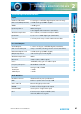
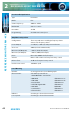
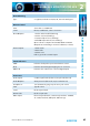
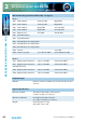
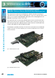
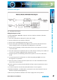
Table Of Contents
- Fig A: Packing List
- Fig B: Power Connections
- Fig C: Mains Lead Table
- Fig 1-1: RB-2S4 Reference Monitor Front Panel
- Fig 1-2: RB-2S10 Reference Monitor Front Panel
- Fig 1-3: Reference Monitor Block Diagram
- Fig 1-4: RM-2S4 Front Panel Controls
- Fig 1-5: RM-2S10 Front Panel Controls
- Fig 1-6: RM-2S4 Source Selector
- Fig 1-7: RM-2S10 Source Selector
- Fig 1-8: RM-2S4 & RM-2S10 Meters
- Fig 1-9: RM-2S4 & RM-2S10 DIPSwitch Settings
- Fig 1-10: Meter Labelling Options
- Fig 1-11: Brightness Control
- Fig 1-13: Balance Control
- Fig 1-12: Phase Meter Display
- Fig 1-14: Status LEDs
- Fig 1-15: RB-2S4 & RB-2S10 Modifier Switches
- Fig 1-16: Reference Monitor RM-2S4 Rear
- Fig 1-17: Reference Monitor RM-2S10 Rear
- Fig 1-18: RM-2S4 & RM-2S10 DIPswitch Settings
- Fig 2-1: RB-4C8 Reference Monitor Front Panel
- Fig 2-2: Reference Monitor Block Diagram
- Fig 2-3: RM-4C8 Front Panel Controls
- Fig 2-4: RM-4C8 Rotary Source Selectors
- Fig 2-5: RM-4C8 Meters
- Fig 2-6: RM-4C8 DIPSwitch Settings
- Fig 2-7: Meter Labelling Options
- Fig 2-8: Brightness Control
- Fig 2-9: Phase Meter Display
- Fig 2-10: Balance Control
- Fig 2-11: Status LEDs
- Fig 2-12: RB-4C8 Modifier Switches
- Fig 2-13: Reference Monitor RM-4C8 Rear
- Fig 3-1: RM-HD1 Expansion Card
- Fig 3-2: RM-HDE1 Expansion Card
- Fig 3-3: Reference Monitor RM-HD(E)1 Block Diagram
- Warranty
- Safety Information
- Installation Information
- Reference Monitors Introduction
- RM-2S4 Reference Monitor, 2 LED meters & 4 stereo
- channel inputs
- RM-2S10 Reference Monitor, 2 LED meters & 10 stereo
- channel inputs
- Technical Specification RM-2S4 & RM-2S10
- RB-4C8 Reference Monitor, 4 LED meters, 8 channel inputs &
- dual selectors
- Technical Specification RM-4C8
- RM-HD1 Reference Monitor HD-SDI Expansion Card &
- RM-HDE1 Reference Monitor HD-SDI & Dolby E Expansion Card
- Technical Specification RM-HD1 & RM-HDE1
- Serial Interface Commands & Responses Protocol

Reference Monitors User Handbook
47
REFERENCE MONITORS RM-4C8
2
Reference Monitors User Handbook
47
REFERENCE MONITORS RM-HD(E)1
REFERENCE MONITORS RM-HD(E)1
3
System Block Diagram
Fig 3-3: RM-HD(E)1 Block Diagram
Fitting The Expansion Card
To install an RM-HD1 or RM-HDE1 expansion card into a Reference Monitor, follow the
procedure below.
1) Disconnect the Reference Monitor from the mains supply.
2) Remove all the lid screws and take o the lid.
3) Remove the rear blanking plate (4 x M3 x 6 screws).
4) Remove the nylock nut from the main PCB (second one in from the left of the unit
when looking from the rear) and t the 27mm M3 pillar on to the stud.
5) Remove the self tapping screw from the plastic mount on the expansion board and
remove the plate.
6) Place the expansion board plate into the rear of the unit (do not x it yet as it will need
to be loose to aid in the alignment of the expansion board).
7) Plug the expansion board trailing cable into the expansion connector on the main
board.
8) Insert the expansion board into the rear of the unit, putting the BNC connectors
through the loose plate rst.
9) Once in position, screw the expansion plate to the rear of the unit with the 4 x M3 x
6mm screws removed earlier.
10) Fix the expansion board to the plate with the self tap screw into the plastic mount on
the board.
11) Screw the expansion board to the pillar with the M3 x 6 screw supplied.
12) Ret the lid with the 19 o M3 x 8mm countersunk screws. Ensure that all screws are
tted loosely before nally tightening.
13) Reconnect your Reference Monitor to the mains supply and check operation.