
Manual
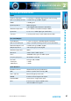
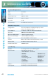
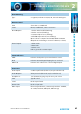
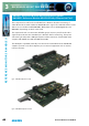
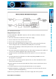
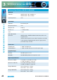
Table Of Contents
- Fig A: Packing List
- Fig B: Power Connections
- Fig C: Mains Lead Table
- Fig 1-1: RB-2S4 Reference Monitor Front Panel
- Fig 1-2: RB-2S10 Reference Monitor Front Panel
- Fig 1-3: Reference Monitor Block Diagram
- Fig 1-4: RM-2S4 Front Panel Controls
- Fig 1-5: RM-2S10 Front Panel Controls
- Fig 1-6: RM-2S4 Source Selector
- Fig 1-7: RM-2S10 Source Selector
- Fig 1-8: RM-2S4 & RM-2S10 Meters
- Fig 1-9: RM-2S4 & RM-2S10 DIPSwitch Settings
- Fig 1-10: Meter Labelling Options
- Fig 1-11: Brightness Control
- Fig 1-13: Balance Control
- Fig 1-12: Phase Meter Display
- Fig 1-14: Status LEDs
- Fig 1-15: RB-2S4 & RB-2S10 Modifier Switches
- Fig 1-16: Reference Monitor RM-2S4 Rear
- Fig 1-17: Reference Monitor RM-2S10 Rear
- Fig 1-18: RM-2S4 & RM-2S10 DIPswitch Settings
- Fig 2-1: RB-4C8 Reference Monitor Front Panel
- Fig 2-2: Reference Monitor Block Diagram
- Fig 2-3: RM-4C8 Front Panel Controls
- Fig 2-4: RM-4C8 Rotary Source Selectors
- Fig 2-5: RM-4C8 Meters
- Fig 2-6: RM-4C8 DIPSwitch Settings
- Fig 2-7: Meter Labelling Options
- Fig 2-8: Brightness Control
- Fig 2-9: Phase Meter Display
- Fig 2-10: Balance Control
- Fig 2-11: Status LEDs
- Fig 2-12: RB-4C8 Modifier Switches
- Fig 2-13: Reference Monitor RM-4C8 Rear
- Fig 3-1: RM-HD1 Expansion Card
- Fig 3-2: RM-HDE1 Expansion Card
- Fig 3-3: Reference Monitor RM-HD(E)1 Block Diagram
- Warranty
- Safety Information
- Installation Information
- Reference Monitors Introduction
- RM-2S4 Reference Monitor, 2 LED meters & 4 stereo
- channel inputs
- RM-2S10 Reference Monitor, 2 LED meters & 10 stereo
- channel inputs
- Technical Specification RM-2S4 & RM-2S10
- RB-4C8 Reference Monitor, 4 LED meters, 8 channel inputs &
- dual selectors
- Technical Specification RM-4C8
- RM-HD1 Reference Monitor HD-SDI Expansion Card &
- RM-HDE1 Reference Monitor HD-SDI & Dolby E Expansion Card
- Technical Specification RM-HD1 & RM-HDE1
- Serial Interface Commands & Responses Protocol

Reference Monitors User Handbook
43
REFERENCE MONITORS RM-4C8
REFERENCE MONITORS RM-4C8
2
Phase Metering
Type: 5-segment, indication at 0, 45, 90, 135 and 180 degrees.
Remote Control
USB: Slave device, 19200 baud
Serial: RS232, 19200 baud, 3-wire connection
Alarm Outputs: 1. Audio underlevel/fail (latching)
2. Audio overlevel (latching)
3. Sustained phase error (latching)
4. AES/EBU input unlock (non-latching)
Open-collector outputs rated at 30V, 50mA maximum
Output low/conducting in normal condition (no alarm)
Control Inputs: 1. Mute audio
2. Dim audio
3. Alarm reset
Pull-to-ground to activate inputs
Status Indicators
LIMIT: Indicates loudspeaker protection limiter is active.
CLIP: Indicates internal digital clipping due to overlevel.
LOCK L/R: Indicates lock achieved on selected digital inputs.
Connectors
Audio Inputs: 8 x XLR 3-pin female (balanced, may be unbalanced)
Audio Outputs: XLR 3-pin male (balanced, may be unbalanced)
Headphones: 1/4” (6.35mm) A-gauge 3-pole stereo jack socket
USB: Type B socket.
Serial: D-sub 9-pin female.
Remote I/O: D-sub 15-pin male.
Mains Input: Filtered 3-pin IEC male, continuously rated 85 - 264VAC,
47 - 63Hz, fused 2A, 60W peak, 30W average