
Manual
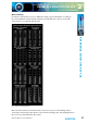
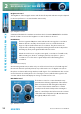
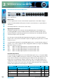

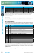
Table Of Contents
- Fig A: Packing List
- Fig B: Power Connections
- Fig C: Mains Lead Table
- Fig 1-1: RB-2S4 Reference Monitor Front Panel
- Fig 1-2: RB-2S10 Reference Monitor Front Panel
- Fig 1-3: Reference Monitor Block Diagram
- Fig 1-4: RM-2S4 Front Panel Controls
- Fig 1-5: RM-2S10 Front Panel Controls
- Fig 1-6: RM-2S4 Source Selector
- Fig 1-7: RM-2S10 Source Selector
- Fig 1-8: RM-2S4 & RM-2S10 Meters
- Fig 1-9: RM-2S4 & RM-2S10 DIPSwitch Settings
- Fig 1-10: Meter Labelling Options
- Fig 1-11: Brightness Control
- Fig 1-13: Balance Control
- Fig 1-12: Phase Meter Display
- Fig 1-14: Status LEDs
- Fig 1-15: RB-2S4 & RB-2S10 Modifier Switches
- Fig 1-16: Reference Monitor RM-2S4 Rear
- Fig 1-17: Reference Monitor RM-2S10 Rear
- Fig 1-18: RM-2S4 & RM-2S10 DIPswitch Settings
- Fig 2-1: RB-4C8 Reference Monitor Front Panel
- Fig 2-2: Reference Monitor Block Diagram
- Fig 2-3: RM-4C8 Front Panel Controls
- Fig 2-4: RM-4C8 Rotary Source Selectors
- Fig 2-5: RM-4C8 Meters
- Fig 2-6: RM-4C8 DIPSwitch Settings
- Fig 2-7: Meter Labelling Options
- Fig 2-8: Brightness Control
- Fig 2-9: Phase Meter Display
- Fig 2-10: Balance Control
- Fig 2-11: Status LEDs
- Fig 2-12: RB-4C8 Modifier Switches
- Fig 2-13: Reference Monitor RM-4C8 Rear
- Fig 3-1: RM-HD1 Expansion Card
- Fig 3-2: RM-HDE1 Expansion Card
- Fig 3-3: Reference Monitor RM-HD(E)1 Block Diagram
- Warranty
- Safety Information
- Installation Information
- Reference Monitors Introduction
- RM-2S4 Reference Monitor, 2 LED meters & 4 stereo
- channel inputs
- RM-2S10 Reference Monitor, 2 LED meters & 10 stereo
- channel inputs
- Technical Specification RM-2S4 & RM-2S10
- RB-4C8 Reference Monitor, 4 LED meters, 8 channel inputs &
- dual selectors
- Technical Specification RM-4C8
- RM-HD1 Reference Monitor HD-SDI Expansion Card &
- RM-HDE1 Reference Monitor HD-SDI & Dolby E Expansion Card
- Technical Specification RM-HD1 & RM-HDE1
- Serial Interface Commands & Responses Protocol

Reference Monitors User Handbook
37
REFERENCE MONITORS RM-4C8
REFERENCE MONITORS RM-4C8
2
Note that the application of extra input gain reduces the maximum signal level permitted
before signal clipping occurs. The front panel CLIP indicator illuminates at the onset of
clipping, with extended illumination indicating that the input gain should be reduced and/
or the input signal levels attenuated.
Audio Inputs
Three-pin female XLR connectors are provided for the connection of up to eight balanced
audio Sources in two Banks (A and B) of four. The pin assignations are as follows:
Pin 1: Ground
Pin 2: In-phase signal (“hot”)
Pin 3: Out-of-phase signal (“cold”)
Unbalanced signals may also be used by linking pins 1 and 3 and applying the unbalanced
signal to pin 2.
Each Source input accepts an analogue line-level signal, which may be a complete
monophonic signal or one half of a stereo pair. Two of the four XLRs in each Bank also
accept AES/EBU digital signals, the two channels of which are automatically routed to a pair
of Source channels as per the connector labelling.
The RM-4C8 automatically detects digital input signals and seamlessly presents them
for selection in exactly the same way as analogue ones; the inputs may therefore be
any mixture of analogue and digital Sources. A full-scale digital input signal (0dBFS)
corresponds to the maximum analogue input signal level of +18dBu (with no extra input
gain applied).
Line Level Audio Outputs
A pair of three-pin male XLR connectors provides a stereo line-level audio output carrying
the selected audio Source signals. The XLR pin assignations are as follows:
Pin 1: Ground
Pin 2: In-phase signal (“hot”)
Pin 3: Out-of-phase signal (“cold”)
The signals may be unbalanced without loss of level by linking pins 1 and 3 and taking the
unbalanced signal from pin 2.
The line-level outputs may be congured either as analogue (using both output XLRs)
or AES/EBU digital (attach to the left-hand XLR of the pair and leave the right-hand XLR
unconnected). The selection of format is determined by the setting of switches 1-4 in Block
1 of the conguration switches (see Fig 2-6), according to the following table. Switch 5 in
the same block determines whether the line-level outputs are xed in level or proportional
in level to the setting of the volume control. Power should be removed from the unit while
making changes to the conguration switches and reapplied once the changes
are complete.