
Manual
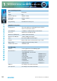
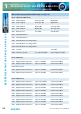
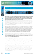
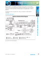
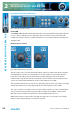
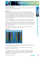
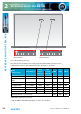
Table Of Contents
- Fig A: Packing List
- Fig B: Power Connections
- Fig C: Mains Lead Table
- Fig 1-1: RB-2S4 Reference Monitor Front Panel
- Fig 1-2: RB-2S10 Reference Monitor Front Panel
- Fig 1-3: Reference Monitor Block Diagram
- Fig 1-4: RM-2S4 Front Panel Controls
- Fig 1-5: RM-2S10 Front Panel Controls
- Fig 1-6: RM-2S4 Source Selector
- Fig 1-7: RM-2S10 Source Selector
- Fig 1-8: RM-2S4 & RM-2S10 Meters
- Fig 1-9: RM-2S4 & RM-2S10 DIPSwitch Settings
- Fig 1-10: Meter Labelling Options
- Fig 1-11: Brightness Control
- Fig 1-13: Balance Control
- Fig 1-12: Phase Meter Display
- Fig 1-14: Status LEDs
- Fig 1-15: RB-2S4 & RB-2S10 Modifier Switches
- Fig 1-16: Reference Monitor RM-2S4 Rear
- Fig 1-17: Reference Monitor RM-2S10 Rear
- Fig 1-18: RM-2S4 & RM-2S10 DIPswitch Settings
- Fig 2-1: RB-4C8 Reference Monitor Front Panel
- Fig 2-2: Reference Monitor Block Diagram
- Fig 2-3: RM-4C8 Front Panel Controls
- Fig 2-4: RM-4C8 Rotary Source Selectors
- Fig 2-5: RM-4C8 Meters
- Fig 2-6: RM-4C8 DIPSwitch Settings
- Fig 2-7: Meter Labelling Options
- Fig 2-8: Brightness Control
- Fig 2-9: Phase Meter Display
- Fig 2-10: Balance Control
- Fig 2-11: Status LEDs
- Fig 2-12: RB-4C8 Modifier Switches
- Fig 2-13: Reference Monitor RM-4C8 Rear
- Fig 3-1: RM-HD1 Expansion Card
- Fig 3-2: RM-HDE1 Expansion Card
- Fig 3-3: Reference Monitor RM-HD(E)1 Block Diagram
- Warranty
- Safety Information
- Installation Information
- Reference Monitors Introduction
- RM-2S4 Reference Monitor, 2 LED meters & 4 stereo
- channel inputs
- RM-2S10 Reference Monitor, 2 LED meters & 10 stereo
- channel inputs
- Technical Specification RM-2S4 & RM-2S10
- RB-4C8 Reference Monitor, 4 LED meters, 8 channel inputs &
- dual selectors
- Technical Specification RM-4C8
- RM-HD1 Reference Monitor HD-SDI Expansion Card &
- RM-HDE1 Reference Monitor HD-SDI & Dolby E Expansion Card
- Technical Specification RM-HD1 & RM-HDE1
- Serial Interface Commands & Responses Protocol

30
Reference Monitors User Handbook
REFERENCE MONITORS RM-4C8
REFERENCE MONITORS RM-4C8
2
Fig 2-6: RM-4C8 DIPSwitch Settings
Note that power should be removed from the unit while making changes to the
conguration switches and reapplied once the changes are complete.
Meter
Characteristic
Scale Range*
Amber
section
starts at*
Red
section
starts at*
SW8 SW9 SW10
Dual PPM + VU -12 to +13dBu 0dBu +8dBu OFF OFF OFF
BBC PPM or EBU
PPM**
-12 to +13dBu 0dBu +8dBu ON OFF OFF
Nordic PPM -38 to +12dBu 0dBu +8dBu OFF ON OFF
AES Digital PPM -50 to 0dBFS -2dBFS 0dBFS ON ON OFF
DIN PPM -50 to +5dBu 0dBu +4dBu OFF OFF ON
Standard VU -22 to +3VU -4VU 0VU ON OFF ON
Extended VU -55 to +15VU -3VU +1VU OFF ON ON
Currently unused – do not select ON ON ON
* With 0dB of input gain selected.
** May be BBC or EBU PPM depending on choice of scale plate.
1
ON DIP
2 3 4 5 6 7 8 9 10 11 12 1
ON DIP
2 3 4 5 6 7 8 9 10 11 12
1
ON DIP
2 3 4 5 6 7 8 9
10 11 12 1
ON DIP
2 3 4 5 6 7 8 9
10 11 12
Reference Monitor underside
DIPSwitch Block 1 DIPSwitch Block 2