
Manual
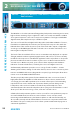
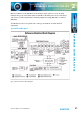
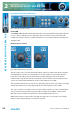
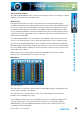
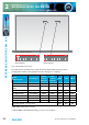
Table Of Contents
- Fig A: Packing List
- Fig B: Power Connections
- Fig C: Mains Lead Table
- Fig 1-1: RB-2S4 Reference Monitor Front Panel
- Fig 1-2: RB-2S10 Reference Monitor Front Panel
- Fig 1-3: Reference Monitor Block Diagram
- Fig 1-4: RM-2S4 Front Panel Controls
- Fig 1-5: RM-2S10 Front Panel Controls
- Fig 1-6: RM-2S4 Source Selector
- Fig 1-7: RM-2S10 Source Selector
- Fig 1-8: RM-2S4 & RM-2S10 Meters
- Fig 1-9: RM-2S4 & RM-2S10 DIPSwitch Settings
- Fig 1-10: Meter Labelling Options
- Fig 1-11: Brightness Control
- Fig 1-13: Balance Control
- Fig 1-12: Phase Meter Display
- Fig 1-14: Status LEDs
- Fig 1-15: RB-2S4 & RB-2S10 Modifier Switches
- Fig 1-16: Reference Monitor RM-2S4 Rear
- Fig 1-17: Reference Monitor RM-2S10 Rear
- Fig 1-18: RM-2S4 & RM-2S10 DIPswitch Settings
- Fig 2-1: RB-4C8 Reference Monitor Front Panel
- Fig 2-2: Reference Monitor Block Diagram
- Fig 2-3: RM-4C8 Front Panel Controls
- Fig 2-4: RM-4C8 Rotary Source Selectors
- Fig 2-5: RM-4C8 Meters
- Fig 2-6: RM-4C8 DIPSwitch Settings
- Fig 2-7: Meter Labelling Options
- Fig 2-8: Brightness Control
- Fig 2-9: Phase Meter Display
- Fig 2-10: Balance Control
- Fig 2-11: Status LEDs
- Fig 2-12: RB-4C8 Modifier Switches
- Fig 2-13: Reference Monitor RM-4C8 Rear
- Fig 3-1: RM-HD1 Expansion Card
- Fig 3-2: RM-HDE1 Expansion Card
- Fig 3-3: Reference Monitor RM-HD(E)1 Block Diagram
- Warranty
- Safety Information
- Installation Information
- Reference Monitors Introduction
- RM-2S4 Reference Monitor, 2 LED meters & 4 stereo
- channel inputs
- RM-2S10 Reference Monitor, 2 LED meters & 10 stereo
- channel inputs
- Technical Specification RM-2S4 & RM-2S10
- RB-4C8 Reference Monitor, 4 LED meters, 8 channel inputs &
- dual selectors
- Technical Specification RM-4C8
- RM-HD1 Reference Monitor HD-SDI Expansion Card &
- RM-HDE1 Reference Monitor HD-SDI & Dolby E Expansion Card
- Technical Specification RM-HD1 & RM-HDE1
- Serial Interface Commands & Responses Protocol

Reference Monitors User Handbook
29
REFERENCE MONITORS RM-4C8
REFERENCE MONITORS RM-4C8
2
Auto-Selection of Inputs
As standard, the RM-4C8 has auto-selection of the inputs, i.e. whichever analogue or digital
signal is connected to the input will be used.
Bank Selector
Pressing the left-hand Source selector knob inwards steps sequentially through all
available input Banks (groups of four inputs). Each press moves the selected Bank onwards
by one step; once the last available Bank is selected, a further press returns the selection
to the rst available Bank. The currently selected Bank is indicated by illumination of the
corresponding Bank LED. The currently selected Bank may also be changed via the remote
control ports (see the appropriate sections of this manual), and such changes will also be
reected by the Bank LEDs.
As standard, the RM-4C8 possesses two Banks, A and B. Both comprise four monophonic
Sources, each of which may be a mono analogue signal, part of a stereo analogue signal,
part of a stereo AES/EBU digital signal or any combination thereof. Attaching a valid AES/
EBU digital signal automatically assigns its two channels to a pair of Sources. Further Banks
become available with the addition of optional expansion cards. It is not possible to select
Banks which are not tted.
When mains power is removed, the currently selected Bank is stored in non-volatile
memory and recalled instantly once power is restored.
Main Meters
Fig 2-5: RM-4C8 Meters
The main meters are quad 26-segment, multicoloured LED bargraphs, displaying the four
Sources in the currently selected Bank.
The meters behave as “input” meters, i.e. they are not aected by front panel signal
Modiers such as Middle+Side or Cut.
Several dierent characteristics are available for the meters to suit dierent applications
and regional preferences. The active meter characteristic is selected by the settings
of DIPSwitches 8, 9 and 10 on DIPSwitch Block 1 (found on the underside of the unit),
according to the following table.