
Manual
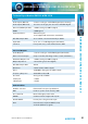
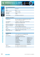
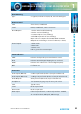
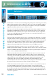
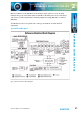
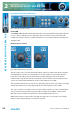
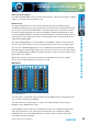
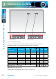
Table Of Contents
- Fig A: Packing List
- Fig B: Power Connections
- Fig C: Mains Lead Table
- Fig 1-1: RB-2S4 Reference Monitor Front Panel
- Fig 1-2: RB-2S10 Reference Monitor Front Panel
- Fig 1-3: Reference Monitor Block Diagram
- Fig 1-4: RM-2S4 Front Panel Controls
- Fig 1-5: RM-2S10 Front Panel Controls
- Fig 1-6: RM-2S4 Source Selector
- Fig 1-7: RM-2S10 Source Selector
- Fig 1-8: RM-2S4 & RM-2S10 Meters
- Fig 1-9: RM-2S4 & RM-2S10 DIPSwitch Settings
- Fig 1-10: Meter Labelling Options
- Fig 1-11: Brightness Control
- Fig 1-13: Balance Control
- Fig 1-12: Phase Meter Display
- Fig 1-14: Status LEDs
- Fig 1-15: RB-2S4 & RB-2S10 Modifier Switches
- Fig 1-16: Reference Monitor RM-2S4 Rear
- Fig 1-17: Reference Monitor RM-2S10 Rear
- Fig 1-18: RM-2S4 & RM-2S10 DIPswitch Settings
- Fig 2-1: RB-4C8 Reference Monitor Front Panel
- Fig 2-2: Reference Monitor Block Diagram
- Fig 2-3: RM-4C8 Front Panel Controls
- Fig 2-4: RM-4C8 Rotary Source Selectors
- Fig 2-5: RM-4C8 Meters
- Fig 2-6: RM-4C8 DIPSwitch Settings
- Fig 2-7: Meter Labelling Options
- Fig 2-8: Brightness Control
- Fig 2-9: Phase Meter Display
- Fig 2-10: Balance Control
- Fig 2-11: Status LEDs
- Fig 2-12: RB-4C8 Modifier Switches
- Fig 2-13: Reference Monitor RM-4C8 Rear
- Fig 3-1: RM-HD1 Expansion Card
- Fig 3-2: RM-HDE1 Expansion Card
- Fig 3-3: Reference Monitor RM-HD(E)1 Block Diagram
- Warranty
- Safety Information
- Installation Information
- Reference Monitors Introduction
- RM-2S4 Reference Monitor, 2 LED meters & 4 stereo
- channel inputs
- RM-2S10 Reference Monitor, 2 LED meters & 10 stereo
- channel inputs
- Technical Specification RM-2S4 & RM-2S10
- RB-4C8 Reference Monitor, 4 LED meters, 8 channel inputs &
- dual selectors
- Technical Specification RM-4C8
- RM-HD1 Reference Monitor HD-SDI Expansion Card &
- RM-HDE1 Reference Monitor HD-SDI & Dolby E Expansion Card
- Technical Specification RM-HD1 & RM-HDE1
- Serial Interface Commands & Responses Protocol

24
Reference Monitors User Handbook
REFERENCE MONITORS RM-2S4 & RM-2S10
REFERENCE MONITORS RM-2S4 & RM-2S10
1
DIP Switch Settings (Underneath The Unit, See Fig 1-17)
Block 1 (RM-2S4 & RM-2S10)
SW1 Audio Output Analogue ON Digital OFF
SW2 Audio Output Analogue ON Digital OFF
SW3 Audio Output Digital ON Analogue OFF
SW4 Audio Output Digital ON Analogue OFF
SW5 Output Level Fixed ON Variable OFF
SW6 Input Gain Matrix
SW7 Input Gain Matrix
SW8 Meter Ballistics & Scaling Matrix
SW9 Meter Ballistics & Scaling Matrix
SW10 Meter Ballistics & Scaling Matrix
SW11 Unused Set to OFF
SW12 Firmware Update Force Bootload ON Normal Operation OFF
Block 2 (RM-2S4)
SW1 Digital Input Termination Input 1 110Ω ON Unterminated OFF
SW2 Digital Input Termination Input 2 110Ω ON Unterminated OFF
SW3-SW10 Unused
SW11 Digital Input Termination Input 3 110Ω ON Unterminated OFF
SW12 Digital Input Termination Input 4 110Ω ON Unterminated OFF
Block 2 (RM-2S10)
SW1 Digital Input Termination Input 10 110Ω ON Unterminated OFF
SW2 Digital Input Termination Input 9 110Ω ON Unterminated OFF
SW3 Digital Input Termination Input 8 110Ω ON Unterminated OFF
SW4 Digital Input Termination Input 7 110Ω ON Unterminated OFF
SW5 Digital Input Termination Input 6 110Ω ON Unterminated OFF
SW6 Digital Input Termination Input 5 110Ω ON Unterminated OFF
SW7 Digital Input Termination Input 4 110Ω ON Unterminated OFF
SW8 Digital Input Termination Input 3 110Ω ON Unterminated OFF
SW9 Digital Input Termination Input 2 110Ω ON Unterminated OFF