
Manual
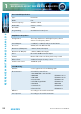
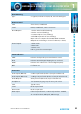
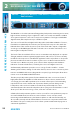
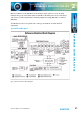
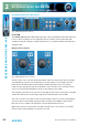
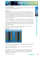
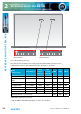
Table Of Contents
- Fig A: Packing List
- Fig B: Power Connections
- Fig C: Mains Lead Table
- Fig 1-1: RB-2S4 Reference Monitor Front Panel
- Fig 1-2: RB-2S10 Reference Monitor Front Panel
- Fig 1-3: Reference Monitor Block Diagram
- Fig 1-4: RM-2S4 Front Panel Controls
- Fig 1-5: RM-2S10 Front Panel Controls
- Fig 1-6: RM-2S4 Source Selector
- Fig 1-7: RM-2S10 Source Selector
- Fig 1-8: RM-2S4 & RM-2S10 Meters
- Fig 1-9: RM-2S4 & RM-2S10 DIPSwitch Settings
- Fig 1-10: Meter Labelling Options
- Fig 1-11: Brightness Control
- Fig 1-13: Balance Control
- Fig 1-12: Phase Meter Display
- Fig 1-14: Status LEDs
- Fig 1-15: RB-2S4 & RB-2S10 Modifier Switches
- Fig 1-16: Reference Monitor RM-2S4 Rear
- Fig 1-17: Reference Monitor RM-2S10 Rear
- Fig 1-18: RM-2S4 & RM-2S10 DIPswitch Settings
- Fig 2-1: RB-4C8 Reference Monitor Front Panel
- Fig 2-2: Reference Monitor Block Diagram
- Fig 2-3: RM-4C8 Front Panel Controls
- Fig 2-4: RM-4C8 Rotary Source Selectors
- Fig 2-5: RM-4C8 Meters
- Fig 2-6: RM-4C8 DIPSwitch Settings
- Fig 2-7: Meter Labelling Options
- Fig 2-8: Brightness Control
- Fig 2-9: Phase Meter Display
- Fig 2-10: Balance Control
- Fig 2-11: Status LEDs
- Fig 2-12: RB-4C8 Modifier Switches
- Fig 2-13: Reference Monitor RM-4C8 Rear
- Fig 3-1: RM-HD1 Expansion Card
- Fig 3-2: RM-HDE1 Expansion Card
- Fig 3-3: Reference Monitor RM-HD(E)1 Block Diagram
- Warranty
- Safety Information
- Installation Information
- Reference Monitors Introduction
- RM-2S4 Reference Monitor, 2 LED meters & 4 stereo
- channel inputs
- RM-2S10 Reference Monitor, 2 LED meters & 10 stereo
- channel inputs
- Technical Specification RM-2S4 & RM-2S10
- RB-4C8 Reference Monitor, 4 LED meters, 8 channel inputs &
- dual selectors
- Technical Specification RM-4C8
- RM-HD1 Reference Monitor HD-SDI Expansion Card &
- RM-HDE1 Reference Monitor HD-SDI & Dolby E Expansion Card
- Technical Specification RM-HD1 & RM-HDE1
- Serial Interface Commands & Responses Protocol

Reference Monitors User Handbook
21
REFERENCE MONITORS RM-2S4 & RM-2S10
REFERENCE MONITORS RM-2S4 & RM-2S10
1
Technical Specication RM-2S4 & RM-2S10
Inputs
Audio Inputs (RM-2S4): 4 x stereo analogue or AES/EBU digital (autoselecting)
Audio Inputs (RM-2S10): 10 x stereo analogue, plus 10 x stereo AES/EBU digital
Max Level (0dB Input Gain): +18dBu (analogue)/0dBFS (digital)
CMRR: >60dB typical
Input Impedance: 20kΩ (analogue)
110 Ω (digital with termination switchable)
AES/EBU Sample Rate: 32 to 192kHz, converted internally to 48kHz
Input Gain: 0, +6, +12 or +18dB digital gain (switchable)
Selection: Front panel rotary control with indicator LEDs
Line Level Outputs
Audio Outputs: 1 x stereo analogue or AES/EBU digital (switchable)
Gain re Selected Input: Unity or variable, following volume control (switchable)
Maximum Output Level: +18dBu (analogue)/0dBFS (digital)
Output Impedance: <50 Ω (analogue)/110 Ω (digital)
AES/EBU Sample Rate: 48kHz
Distortion: <0.02% (1kHz, +8dBu output)
Noise: -84dB RMS, unity gain ref +8dBu output
Frequency Response: 20Hz-20kHz +0/-0.5dB
Crosstalk: Analogue I/O, ref 0dBu
1kHz Input: <-90dB
10kHz input: <-85dB
Audio Modiers
Modier Selection: Illuminated front panel pushbuttons
DIM: Reduces speaker audio level by 10dB
CUT L & CUT R: Mutes left/right speaker audio
MONO: Combines left and right audio inputs
PHASE INVERT: Inverts phase of right audio input
M+S: Converts stereo input to Middle (sum)
and Side (dierence) signals