
Manual
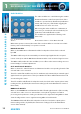
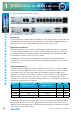
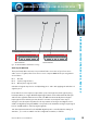
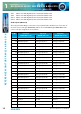
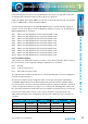
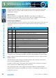
Table Of Contents
- Fig A: Packing List
- Fig B: Power Connections
- Fig C: Mains Lead Table
- Fig 1-1: RB-2S4 Reference Monitor Front Panel
- Fig 1-2: RB-2S10 Reference Monitor Front Panel
- Fig 1-3: Reference Monitor Block Diagram
- Fig 1-4: RM-2S4 Front Panel Controls
- Fig 1-5: RM-2S10 Front Panel Controls
- Fig 1-6: RM-2S4 Source Selector
- Fig 1-7: RM-2S10 Source Selector
- Fig 1-8: RM-2S4 & RM-2S10 Meters
- Fig 1-9: RM-2S4 & RM-2S10 DIPSwitch Settings
- Fig 1-10: Meter Labelling Options
- Fig 1-11: Brightness Control
- Fig 1-13: Balance Control
- Fig 1-12: Phase Meter Display
- Fig 1-14: Status LEDs
- Fig 1-15: RB-2S4 & RB-2S10 Modifier Switches
- Fig 1-16: Reference Monitor RM-2S4 Rear
- Fig 1-17: Reference Monitor RM-2S10 Rear
- Fig 1-18: RM-2S4 & RM-2S10 DIPswitch Settings
- Fig 2-1: RB-4C8 Reference Monitor Front Panel
- Fig 2-2: Reference Monitor Block Diagram
- Fig 2-3: RM-4C8 Front Panel Controls
- Fig 2-4: RM-4C8 Rotary Source Selectors
- Fig 2-5: RM-4C8 Meters
- Fig 2-6: RM-4C8 DIPSwitch Settings
- Fig 2-7: Meter Labelling Options
- Fig 2-8: Brightness Control
- Fig 2-9: Phase Meter Display
- Fig 2-10: Balance Control
- Fig 2-11: Status LEDs
- Fig 2-12: RB-4C8 Modifier Switches
- Fig 2-13: Reference Monitor RM-4C8 Rear
- Fig 3-1: RM-HD1 Expansion Card
- Fig 3-2: RM-HDE1 Expansion Card
- Fig 3-3: Reference Monitor RM-HD(E)1 Block Diagram
- Warranty
- Safety Information
- Installation Information
- Reference Monitors Introduction
- RM-2S4 Reference Monitor, 2 LED meters & 4 stereo
- channel inputs
- RM-2S10 Reference Monitor, 2 LED meters & 10 stereo
- channel inputs
- Technical Specification RM-2S4 & RM-2S10
- RB-4C8 Reference Monitor, 4 LED meters, 8 channel inputs &
- dual selectors
- Technical Specification RM-4C8
- RM-HD1 Reference Monitor HD-SDI Expansion Card &
- RM-HDE1 Reference Monitor HD-SDI & Dolby E Expansion Card
- Technical Specification RM-HD1 & RM-HDE1
- Serial Interface Commands & Responses Protocol

Reference Monitors User Handbook
19
REFERENCE MONITORS RM-2S4 & RM-2S10
REFERENCE MONITORS RM-2S4 & RM-2S10
1
The AES/EBU Lock output is a real-time (non-latching) status output which becomes active
if a valid AES/EBU signal is detected on the currently selected Source input. By default, the
open-collector output is low (conducting) when a valid AES signal is detected, but this
behaviour may be reversed using the serial remote control LCK: command.
The active-low control inputs all have internal pull-ups. Equipment driving these inputs
need sink only 1mA and block 5V.
The MUTE input mutes the loudspeakers and headphones while held low. The front panel
CUT L and CUT R buttons illuminate to indicate that MUTE is asserted.
The DIM input reduces the loudspeaker/headphone level by 10dB while held low (for
example, whilst an external talkback system is active). The front panel DIM button
illuminates to indicate that DIM is asserted.
Asserting the Alarm Reset input by pulling it low resets any active Alarm outputs to their
untriggered states and allows them to monitor for new alarm conditions.
RS232 Remote Control
A 9-way female D-type connector carries a standard RS232 interface via which advanced
conguration options may be set and many functions may be remotely controlled. The pin
assignations are as follows:
Pin 2: Data transmit
Pin 3: Data receive
Pin 5: Ground
All other pins are unused.
The RM-2S4 and RM-2S10 will interface directly with personal computer serial ports at
standard RS232 signal levels using a straight-through cable. The data format is 19200 baud
with 8 data bits, even parity and 1 stop bit. XON/XOFF ow control is used when necessary.
Sonifex SCi software, when installed on a suitable PC, provides straightforward graphical
access to all remote control and conguration options via both RS232 and USB interfaces.
Alternatively, commands may be issued from any text-based terminal program
(e.g. Hyperterminal) or custom software may be developed for specic requirements.