
Manual
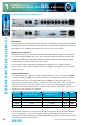
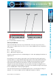
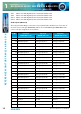
Table Of Contents
- Fig A: Packing List
- Fig B: Power Connections
- Fig C: Mains Lead Table
- Fig 1-1: RB-2S4 Reference Monitor Front Panel
- Fig 1-2: RB-2S10 Reference Monitor Front Panel
- Fig 1-3: Reference Monitor Block Diagram
- Fig 1-4: RM-2S4 Front Panel Controls
- Fig 1-5: RM-2S10 Front Panel Controls
- Fig 1-6: RM-2S4 Source Selector
- Fig 1-7: RM-2S10 Source Selector
- Fig 1-8: RM-2S4 & RM-2S10 Meters
- Fig 1-9: RM-2S4 & RM-2S10 DIPSwitch Settings
- Fig 1-10: Meter Labelling Options
- Fig 1-11: Brightness Control
- Fig 1-13: Balance Control
- Fig 1-12: Phase Meter Display
- Fig 1-14: Status LEDs
- Fig 1-15: RB-2S4 & RB-2S10 Modifier Switches
- Fig 1-16: Reference Monitor RM-2S4 Rear
- Fig 1-17: Reference Monitor RM-2S10 Rear
- Fig 1-18: RM-2S4 & RM-2S10 DIPswitch Settings
- Fig 2-1: RB-4C8 Reference Monitor Front Panel
- Fig 2-2: Reference Monitor Block Diagram
- Fig 2-3: RM-4C8 Front Panel Controls
- Fig 2-4: RM-4C8 Rotary Source Selectors
- Fig 2-5: RM-4C8 Meters
- Fig 2-6: RM-4C8 DIPSwitch Settings
- Fig 2-7: Meter Labelling Options
- Fig 2-8: Brightness Control
- Fig 2-9: Phase Meter Display
- Fig 2-10: Balance Control
- Fig 2-11: Status LEDs
- Fig 2-12: RB-4C8 Modifier Switches
- Fig 2-13: Reference Monitor RM-4C8 Rear
- Fig 3-1: RM-HD1 Expansion Card
- Fig 3-2: RM-HDE1 Expansion Card
- Fig 3-3: Reference Monitor RM-HD(E)1 Block Diagram
- Warranty
- Safety Information
- Installation Information
- Reference Monitors Introduction
- RM-2S4 Reference Monitor, 2 LED meters & 4 stereo
- channel inputs
- RM-2S10 Reference Monitor, 2 LED meters & 10 stereo
- channel inputs
- Technical Specification RM-2S4 & RM-2S10
- RB-4C8 Reference Monitor, 4 LED meters, 8 channel inputs &
- dual selectors
- Technical Specification RM-4C8
- RM-HD1 Reference Monitor HD-SDI Expansion Card &
- RM-HDE1 Reference Monitor HD-SDI & Dolby E Expansion Card
- Technical Specification RM-HD1 & RM-HDE1
- Serial Interface Commands & Responses Protocol

14
Reference Monitors User Handbook
REFERENCE MONITORS RM-2S4 & RM-2S10
REFERENCE MONITORS RM-2S4 & RM-2S10
1
Rear Panel Connections & Operation
Fig 1-16: Reference Monitor RM-2S4 Rear
Fig 1-17: Reference Monitor RM-2S10 Rear
Mains Power
Power is applied via a standard three-pin IEC male socket. Mains voltages between 85V and
264V AC and frequencies between 47 and 63Hz are accepted without adjustment. A 2A, 5 x
20mm SB fuse is used. The Earth pin MUST be connected to ensure safety.
Digital Input Termination
Switchable termination is provided to allow the RM-2S4 & RM-2S10 inputs to be bridged
across an existing AES/EBU connection without double-termination, but this should only
be attempted with the terminating equipment mounted adjacent to the RM-2S4 or RM-
2S10 and with connections kept as short as possible.
It is strongly recommended that the digital input termination is set to ON at all times.
Failure to do so may result in unreliable reception of digital input signals and/or crosstalk
between sources.
Input Gain Adjustment
For both analogue and digital sources the default input gain is zero, i.e. an input of 0dBu
results in a reading of 0dBu on the meters. However, to accommodate lower level sources
it is possible to introduce extra global input gain in 6dB steps. This gain applies to all
inputs and is controlled by the settings of switches 6 and 7 on Block 1 of the conguration
switches (found on the underside of the unit), according to the following table. Power
should be removed from the unit while making changes to the conguration switches and
reapplied once the changes are complete.
Input Gain Maximum Signal Level
(Analogue Sources)
Maximum Signal Level
(Digital Sources)
SW6 SW7
0dB +18dBu 0dBFS OFF OFF
+6dB +12dBu -6dBFS ON OFF
+12dB +6dBu -12dBFS OFF ON
+18dB 0dBu -18dBFS ON ON
Note that the application of extra input gain reduces the maximum signal level permitted
before signal clipping occurs. The front panel CLIP indicator illuminates at the onset of
clipping, with extended illumination indicating that the input gain should be reduced and/
or the input signal levels attenuated.