
Manual
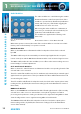
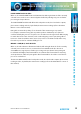
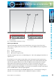
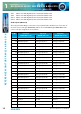
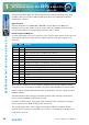
Table Of Contents
- Fig A: Packing List
- Fig B: Power Connections
- Fig C: Mains Lead Table
- Fig 1-1: RB-2S4 Reference Monitor Front Panel
- Fig 1-2: RB-2S10 Reference Monitor Front Panel
- Fig 1-3: Reference Monitor Block Diagram
- Fig 1-4: RM-2S4 Front Panel Controls
- Fig 1-5: RM-2S10 Front Panel Controls
- Fig 1-6: RM-2S4 Source Selector
- Fig 1-7: RM-2S10 Source Selector
- Fig 1-8: RM-2S4 & RM-2S10 Meters
- Fig 1-9: RM-2S4 & RM-2S10 DIPSwitch Settings
- Fig 1-10: Meter Labelling Options
- Fig 1-11: Brightness Control
- Fig 1-13: Balance Control
- Fig 1-12: Phase Meter Display
- Fig 1-14: Status LEDs
- Fig 1-15: RB-2S4 & RB-2S10 Modifier Switches
- Fig 1-16: Reference Monitor RM-2S4 Rear
- Fig 1-17: Reference Monitor RM-2S10 Rear
- Fig 1-18: RM-2S4 & RM-2S10 DIPswitch Settings
- Fig 2-1: RB-4C8 Reference Monitor Front Panel
- Fig 2-2: Reference Monitor Block Diagram
- Fig 2-3: RM-4C8 Front Panel Controls
- Fig 2-4: RM-4C8 Rotary Source Selectors
- Fig 2-5: RM-4C8 Meters
- Fig 2-6: RM-4C8 DIPSwitch Settings
- Fig 2-7: Meter Labelling Options
- Fig 2-8: Brightness Control
- Fig 2-9: Phase Meter Display
- Fig 2-10: Balance Control
- Fig 2-11: Status LEDs
- Fig 2-12: RB-4C8 Modifier Switches
- Fig 2-13: Reference Monitor RM-4C8 Rear
- Fig 3-1: RM-HD1 Expansion Card
- Fig 3-2: RM-HDE1 Expansion Card
- Fig 3-3: Reference Monitor RM-HD(E)1 Block Diagram
- Warranty
- Safety Information
- Installation Information
- Reference Monitors Introduction
- RM-2S4 Reference Monitor, 2 LED meters & 4 stereo
- channel inputs
- RM-2S10 Reference Monitor, 2 LED meters & 10 stereo
- channel inputs
- Technical Specification RM-2S4 & RM-2S10
- RB-4C8 Reference Monitor, 4 LED meters, 8 channel inputs &
- dual selectors
- Technical Specification RM-4C8
- RM-HD1 Reference Monitor HD-SDI Expansion Card &
- RM-HDE1 Reference Monitor HD-SDI & Dolby E Expansion Card
- Technical Specification RM-HD1 & RM-HDE1
- Serial Interface Commands & Responses Protocol

Reference Monitors User Handbook
13
REFERENCE MONITORS RM-2S4 & RM-2S10
REFERENCE MONITORS RM-2S4 & RM-2S10
1
PHASE INVERT Audio Modier
When on, the PHASE INVERT button is illuminated and the right channel of the currently
selected stereo audio Source is inverted (phase shifted by 180 degrees) prior to further
processing and reproduction.
The PHASE INVERT modier will aect the loudspeaker audio, line-level audio outputs,
phase meter reading and also, by default, the main meter readings (refer to the Main
Meters section of this manual).
Being able to invert the polarity of one channel of the monitoring is very useful.
For example, sometimes being able to put the speakers deliberately out of phase is
useful to identify the presence of a phase error elsewhere in the signal chain. When trying
to match the levels of two channels, such as when aligning a stereo pair, being able to
invert one channel and then sum to mono (to produce a cancellation null) makes very
fast and easy work of an otherwise ddly process.
MIDDLE + SIDE (M+S) Audio Modier
When on, the M+S button is illuminated and the left and right channels of the currently
selected stereo audio Source are converted to/from a Middle+Side (also known as
Sum+Dierence) signal prior to further processing and reproduction. An input signal
in standard Left+Right (L+R) format will be encoded into M+S format before metering
and reproduction, while an input signal in M+S format will be decoded to L+R. The two
processes are identical.
The M+S modier will aect the loudspeaker audio, line-level audio outputs, phase meter
reading and also, by default, the main meter readings (refer to the Main Meters section of
this manual).