
Manual
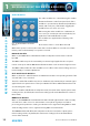
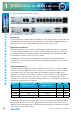
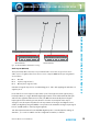
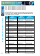
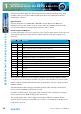
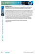
Table Of Contents
- Fig A: Packing List
- Fig B: Power Connections
- Fig C: Mains Lead Table
- Fig 1-1: RB-2S4 Reference Monitor Front Panel
- Fig 1-2: RB-2S10 Reference Monitor Front Panel
- Fig 1-3: Reference Monitor Block Diagram
- Fig 1-4: RM-2S4 Front Panel Controls
- Fig 1-5: RM-2S10 Front Panel Controls
- Fig 1-6: RM-2S4 Source Selector
- Fig 1-7: RM-2S10 Source Selector
- Fig 1-8: RM-2S4 & RM-2S10 Meters
- Fig 1-9: RM-2S4 & RM-2S10 DIPSwitch Settings
- Fig 1-10: Meter Labelling Options
- Fig 1-11: Brightness Control
- Fig 1-13: Balance Control
- Fig 1-12: Phase Meter Display
- Fig 1-14: Status LEDs
- Fig 1-15: RB-2S4 & RB-2S10 Modifier Switches
- Fig 1-16: Reference Monitor RM-2S4 Rear
- Fig 1-17: Reference Monitor RM-2S10 Rear
- Fig 1-18: RM-2S4 & RM-2S10 DIPswitch Settings
- Fig 2-1: RB-4C8 Reference Monitor Front Panel
- Fig 2-2: Reference Monitor Block Diagram
- Fig 2-3: RM-4C8 Front Panel Controls
- Fig 2-4: RM-4C8 Rotary Source Selectors
- Fig 2-5: RM-4C8 Meters
- Fig 2-6: RM-4C8 DIPSwitch Settings
- Fig 2-7: Meter Labelling Options
- Fig 2-8: Brightness Control
- Fig 2-9: Phase Meter Display
- Fig 2-10: Balance Control
- Fig 2-11: Status LEDs
- Fig 2-12: RB-4C8 Modifier Switches
- Fig 2-13: Reference Monitor RM-4C8 Rear
- Fig 3-1: RM-HD1 Expansion Card
- Fig 3-2: RM-HDE1 Expansion Card
- Fig 3-3: Reference Monitor RM-HD(E)1 Block Diagram
- Warranty
- Safety Information
- Installation Information
- Reference Monitors Introduction
- RM-2S4 Reference Monitor, 2 LED meters & 4 stereo
- channel inputs
- RM-2S10 Reference Monitor, 2 LED meters & 10 stereo
- channel inputs
- Technical Specification RM-2S4 & RM-2S10
- RB-4C8 Reference Monitor, 4 LED meters, 8 channel inputs &
- dual selectors
- Technical Specification RM-4C8
- RM-HD1 Reference Monitor HD-SDI Expansion Card &
- RM-HDE1 Reference Monitor HD-SDI & Dolby E Expansion Card
- Technical Specification RM-HD1 & RM-HDE1
- Serial Interface Commands & Responses Protocol

12
Reference Monitors User Handbook
REFERENCE MONITORS RM-2S4 & RM-2S10
REFERENCE MONITORS RM-2S4 & RM-2S10
1
Audio Modiers
The audio modiers are controlled using the 6 white
illuminated buttons on the front panel. Each of the
modiers is operated via an illuminated pushbutton
switch, with each press of the button toggling the
modier from on to o or vice-versa.
When using the audio modiers in combination, it
is necessary to consider the order in which they are
applied since that will aect the results.
The modiers are applied in the following order
(rst > last):
Phase invert > Mono > S+D > Dim > Cut L/R
When mains power is removed, the status of the audio modiers is stored in non-volatile
memory and recalled instantly once power is restored.
DIM Audio Modier
When on, the DIM button is illuminated and the loudspeaker volume level is reduced
by 10dB.
The DIM modier may also be activated by an external signal applied to the rear panel
remote control port and the DIM button illuminates when such an external signal is active.
The DIM modier, unlike the other modiers, has no eect on the meter readings since it is
treated simply as a volume adjustment.
CUT L & CUT R Audio Modiers
When on, the CUT L and CUT buttons are illuminated and the corresponding channel of the
selected audio source is muted.
The CUT L and CUT R modiers may also be simultaneously activated by an external signal
applied to the rear panel remote control port. Both CUT buttons will illuminate when such
an external signal is active.
The CUT modiers will aect the loudspeaker audio, line-level audio outputs, phase meter
reading and also, by default, the main meter readings (refer to the Main Meters section of
this manual).
MONO Audio Modier
When on, the MONO button is illuminated and the left and right channels of the currently
selected stereo audio source are summed into a monophonic signal prior to further
processing and reproduction. Scaling is such that a stereo signal measuring 0dBu on both
channels will generate a mono signal measuring 0dBu on both channels.
The MONO modier will aect the loudspeaker audio, line-level audio outputs, phase
meter reading and also, by default, the main meter readings (refer to the Main Meters
section of this manual).
Fig 1-15: RM-2S4 & RM-2S10 Modier
Switches