
Manual
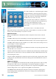
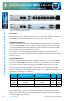
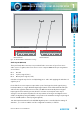
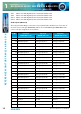
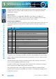
Table Of Contents
- Fig A: Packing List
- Fig B: Power Connections
- Fig C: Mains Lead Table
- Fig 1-1: RB-2S4 Reference Monitor Front Panel
- Fig 1-2: RB-2S10 Reference Monitor Front Panel
- Fig 1-3: Reference Monitor Block Diagram
- Fig 1-4: RM-2S4 Front Panel Controls
- Fig 1-5: RM-2S10 Front Panel Controls
- Fig 1-6: RM-2S4 Source Selector
- Fig 1-7: RM-2S10 Source Selector
- Fig 1-8: RM-2S4 & RM-2S10 Meters
- Fig 1-9: RM-2S4 & RM-2S10 DIPSwitch Settings
- Fig 1-10: Meter Labelling Options
- Fig 1-11: Brightness Control
- Fig 1-13: Balance Control
- Fig 1-12: Phase Meter Display
- Fig 1-14: Status LEDs
- Fig 1-15: RB-2S4 & RB-2S10 Modifier Switches
- Fig 1-16: Reference Monitor RM-2S4 Rear
- Fig 1-17: Reference Monitor RM-2S10 Rear
- Fig 1-18: RM-2S4 & RM-2S10 DIPswitch Settings
- Fig 2-1: RB-4C8 Reference Monitor Front Panel
- Fig 2-2: Reference Monitor Block Diagram
- Fig 2-3: RM-4C8 Front Panel Controls
- Fig 2-4: RM-4C8 Rotary Source Selectors
- Fig 2-5: RM-4C8 Meters
- Fig 2-6: RM-4C8 DIPSwitch Settings
- Fig 2-7: Meter Labelling Options
- Fig 2-8: Brightness Control
- Fig 2-9: Phase Meter Display
- Fig 2-10: Balance Control
- Fig 2-11: Status LEDs
- Fig 2-12: RB-4C8 Modifier Switches
- Fig 2-13: Reference Monitor RM-4C8 Rear
- Fig 3-1: RM-HD1 Expansion Card
- Fig 3-2: RM-HDE1 Expansion Card
- Fig 3-3: Reference Monitor RM-HD(E)1 Block Diagram
- Warranty
- Safety Information
- Installation Information
- Reference Monitors Introduction
- RM-2S4 Reference Monitor, 2 LED meters & 4 stereo
- channel inputs
- RM-2S10 Reference Monitor, 2 LED meters & 10 stereo
- channel inputs
- Technical Specification RM-2S4 & RM-2S10
- RB-4C8 Reference Monitor, 4 LED meters, 8 channel inputs &
- dual selectors
- Technical Specification RM-4C8
- RM-HD1 Reference Monitor HD-SDI Expansion Card &
- RM-HDE1 Reference Monitor HD-SDI & Dolby E Expansion Card
- Technical Specification RM-HD1 & RM-HDE1
- Serial Interface Commands & Responses Protocol

Reference Monitors User Handbook
11
REFERENCE MONITORS RM-2S4 & RM-2S10
REFERENCE MONITORS RM-2S4 & RM-2S10
1
Inserting a plug into the headphone socket automatically mutes the internal loudspeakers.
STATUS LED Indicators
Fig 1-14: Status LEDs
LIMIT indicator
The LIMIT indicator illuminates to show that the loudspeaker protection limiter has been
activated. This happens in response to excessive volume levels, which are a product of the
input signal level and the setting of the volume control, being requested from the unit and
is necessary to prevent permanent damage to the loudspeakers.
The protection limiter is a fast-attack, slow-release type. Brief ashes of the LIMIT indicator
on signal peaks are not cause for concern, but signicant illumination indicates that
the signal is being compressed and that reproduction may be compromised. In those
circumstances the setting of the volume control should be reduced.
CLIP indicator
The CLIP indicator illuminates when the signal level of the currently selected source (taking
into account any input gain applied – refer to the Inputs section of this manual) has either
exceeded or come within 0.5dB of that at which hard clipping occurs.
Analogue input signals will cause clipping if they exceed the maximum acceptable input
level (+18dBu with no additional input gain, reducing by 6dB for every 6dB of input gain
applied). The only solution is to reduce the input level and/or the amount of input gain
being applied; allowing clipping to persist will irreversibly degrade the audio performance.
The digital audio inputs of the RM-2S4 cannot in themselves clip unless extra input gain has
been applied, but signal peaks may come within 0.5dB of maximum if the input signal has
undergone aggressive processing at an earlier stage, and the CLIP indicator will respond
to this.
LOCK indicator
The LOCK indicator illuminates when a valid digital audio signal is present on the currently
selected source input. It will not illuminate if the currently selected Source input is an
analogue signal, or if a digital audio signal is applied which has a sample rate outside the
acceptable range of the unit, contains invalid/non-audio data or is too weak for the receiver
to lock on to.
OPT indicator
The OPT indicator is reserved for future use.