
Manual
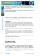
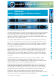
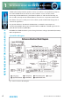
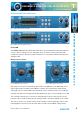
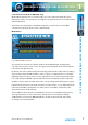
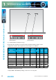
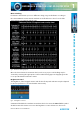
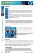
Table Of Contents
- Fig A: Packing List
- Fig B: Power Connections
- Fig C: Mains Lead Table
- Fig 1-1: RB-2S4 Reference Monitor Front Panel
- Fig 1-2: RB-2S10 Reference Monitor Front Panel
- Fig 1-3: Reference Monitor Block Diagram
- Fig 1-4: RM-2S4 Front Panel Controls
- Fig 1-5: RM-2S10 Front Panel Controls
- Fig 1-6: RM-2S4 Source Selector
- Fig 1-7: RM-2S10 Source Selector
- Fig 1-8: RM-2S4 & RM-2S10 Meters
- Fig 1-9: RM-2S4 & RM-2S10 DIPSwitch Settings
- Fig 1-10: Meter Labelling Options
- Fig 1-11: Brightness Control
- Fig 1-13: Balance Control
- Fig 1-12: Phase Meter Display
- Fig 1-14: Status LEDs
- Fig 1-15: RB-2S4 & RB-2S10 Modifier Switches
- Fig 1-16: Reference Monitor RM-2S4 Rear
- Fig 1-17: Reference Monitor RM-2S10 Rear
- Fig 1-18: RM-2S4 & RM-2S10 DIPswitch Settings
- Fig 2-1: RB-4C8 Reference Monitor Front Panel
- Fig 2-2: Reference Monitor Block Diagram
- Fig 2-3: RM-4C8 Front Panel Controls
- Fig 2-4: RM-4C8 Rotary Source Selectors
- Fig 2-5: RM-4C8 Meters
- Fig 2-6: RM-4C8 DIPSwitch Settings
- Fig 2-7: Meter Labelling Options
- Fig 2-8: Brightness Control
- Fig 2-9: Phase Meter Display
- Fig 2-10: Balance Control
- Fig 2-11: Status LEDs
- Fig 2-12: RB-4C8 Modifier Switches
- Fig 2-13: Reference Monitor RM-4C8 Rear
- Fig 3-1: RM-HD1 Expansion Card
- Fig 3-2: RM-HDE1 Expansion Card
- Fig 3-3: Reference Monitor RM-HD(E)1 Block Diagram
- Warranty
- Safety Information
- Installation Information
- Reference Monitors Introduction
- RM-2S4 Reference Monitor, 2 LED meters & 4 stereo
- channel inputs
- RM-2S10 Reference Monitor, 2 LED meters & 10 stereo
- channel inputs
- Technical Specification RM-2S4 & RM-2S10
- RB-4C8 Reference Monitor, 4 LED meters, 8 channel inputs &
- dual selectors
- Technical Specification RM-4C8
- RM-HD1 Reference Monitor HD-SDI Expansion Card &
- RM-HDE1 Reference Monitor HD-SDI & Dolby E Expansion Card
- Technical Specification RM-HD1 & RM-HDE1
- Serial Interface Commands & Responses Protocol

10
Reference Monitors User Handbook
REFERENCE MONITORS RM-2S4 & RM-2S10
REFERENCE MONITORS RM-2S4 & RM-2S10
1
PHASE Meter
The ve-segment LED phase meter indicates the average phase correlation
between the left and right channels of the currently selected stereo audio
source. It is labelled in both degrees of phase shift and amount of correlation.
The phase meter is an “output” meter, reecting exactly what is being heard
from the loudspeakers including any front panel signal modiers that are
active.
A monophonic signal fed to both channels of the selected Source will have
a correlation of 1.0, while inverting one such channel – making it perfectly
out of phase – gives a correlation of -1.0. True stereo signals will produce a
uctuating phase correlation.
Fig 1-12: Phase Meter Display
An interesting situation arises when only one channel of a stereo source is fed with signal.
If the unused channel is perfectly silent (as is possible in the case of a digital source) then
the phase correlation will average 0.0, but a small degree of crosstalk between the used
and unused channels (as is likely in the case of analogue sources) will allow the signal to
self-correlate and the meter will display an average correlation nearer 1.0.
BALANCE Control
The balance control is a centre-detented rotary
potentiometer allowing adjustment of the relative
balance between the left and right loudspeakers.
The control characteristic maintains a constant
overall power from the loudspeakers. Turning the
balance control fully to the left increases the volume
of the left-hand loudspeaker by 6dB and attenuates
the right by 6dB, and vice-versa.
LEVEL Control
The LEVEL, or volume, control is a rotary potentiometer allowing volume adjustment of the
internal loudspeaker system, the headphone output and optionally the line level outputs
(see Line Level Audio Outputs on page 17). A usable control range of 36dB is provided, and
with the volume control in the fully anti-clockwise position the signal is completely muted.
High input signal levels and/or high volume settings may result in activation of the
loudspeaker protection limiter (refer to the Limiter section of this manual).
Headphone Output
The front panel headphone output is a ¼” (6.35mm) stereo jack socket capable of
delivering over 80mW into 32Ω - 600Ω professional headphones at full volume. Higher
impedance headphones may be used at reduced levels. Lower impedance headphones
should not be used.
Fig 1-13: Balance Control