
Manual
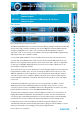
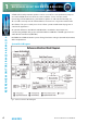
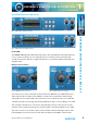
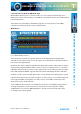
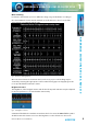
Table Of Contents
- Fig A: Packing List
- Fig B: Power Connections
- Fig C: Mains Lead Table
- Fig 1-1: RB-2S4 Reference Monitor Front Panel
- Fig 1-2: RB-2S10 Reference Monitor Front Panel
- Fig 1-3: Reference Monitor Block Diagram
- Fig 1-4: RM-2S4 Front Panel Controls
- Fig 1-5: RM-2S10 Front Panel Controls
- Fig 1-6: RM-2S4 Source Selector
- Fig 1-7: RM-2S10 Source Selector
- Fig 1-8: RM-2S4 & RM-2S10 Meters
- Fig 1-9: RM-2S4 & RM-2S10 DIPSwitch Settings
- Fig 1-10: Meter Labelling Options
- Fig 1-11: Brightness Control
- Fig 1-13: Balance Control
- Fig 1-12: Phase Meter Display
- Fig 1-14: Status LEDs
- Fig 1-15: RB-2S4 & RB-2S10 Modifier Switches
- Fig 1-16: Reference Monitor RM-2S4 Rear
- Fig 1-17: Reference Monitor RM-2S10 Rear
- Fig 1-18: RM-2S4 & RM-2S10 DIPswitch Settings
- Fig 2-1: RB-4C8 Reference Monitor Front Panel
- Fig 2-2: Reference Monitor Block Diagram
- Fig 2-3: RM-4C8 Front Panel Controls
- Fig 2-4: RM-4C8 Rotary Source Selectors
- Fig 2-5: RM-4C8 Meters
- Fig 2-6: RM-4C8 DIPSwitch Settings
- Fig 2-7: Meter Labelling Options
- Fig 2-8: Brightness Control
- Fig 2-9: Phase Meter Display
- Fig 2-10: Balance Control
- Fig 2-11: Status LEDs
- Fig 2-12: RB-4C8 Modifier Switches
- Fig 2-13: Reference Monitor RM-4C8 Rear
- Fig 3-1: RM-HD1 Expansion Card
- Fig 3-2: RM-HDE1 Expansion Card
- Fig 3-3: Reference Monitor RM-HD(E)1 Block Diagram
- Warranty
- Safety Information
- Installation Information
- Reference Monitors Introduction
- RM-2S4 Reference Monitor, 2 LED meters & 4 stereo
- channel inputs
- RM-2S10 Reference Monitor, 2 LED meters & 10 stereo
- channel inputs
- Technical Specification RM-2S4 & RM-2S10
- RB-4C8 Reference Monitor, 4 LED meters, 8 channel inputs &
- dual selectors
- Technical Specification RM-4C8
- RM-HD1 Reference Monitor HD-SDI Expansion Card &
- RM-HDE1 Reference Monitor HD-SDI & Dolby E Expansion Card
- Technical Specification RM-HD1 & RM-HDE1
- Serial Interface Commands & Responses Protocol

Reference Monitors User Handbook
5
REFERENCE MONITORS RM-2S4 & RM-2S10
REFERENCE MONITORS RM-2S4 & RM-2S10
1
Front Panel Indicators & Controls
Fig 1-4: RM-2S4 Front Panel Controls
Fig 1-5: RM-2S10 Front Panel Controls
Power LED
The POWER LED illuminates whilst internal power is present within the unit. If this indicator
is not on, the most likely reason is simply the absence of mains power, but under fault
conditions it may also indicate a ruptured mains fuse or a problem with the internal power
supply module.
Rotary Source Selector
The rotary Source selector determines which of the four (RM-2S4) or ten (RM-2S10) stereo
audio inputs in the currently selected Bank is routed to the loudspeakers and metering.
Turning the selector anticlockwise increments the Source number and vice versa, with the
currently selected Source being indicated by illumination of the corresponding Source LED.
The currently selected Source can also be changed by the remote control ports (see the
relevant sections of this manual), & such changes will also be reected by the Source LEDs.
The Source selector is an endless rotary encoder; further rotation will be ignored once the
lowest/highest Source has been selected. If the currently selected Bank contains fewer
Fig 1-6: RM-2S4 Source Selector Fig 1-7: RM-2S10 Source Selector