
Manual
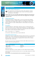
Table Of Contents
- Fig A: Packing List
- Fig B: Power Connections
- Fig C: Mains Lead Table
- Fig 1-1: RB-2S4 Reference Monitor Front Panel
- Fig 1-2: RB-2S10 Reference Monitor Front Panel
- Fig 1-3: Reference Monitor Block Diagram
- Fig 1-4: RM-2S4 Front Panel Controls
- Fig 1-5: RM-2S10 Front Panel Controls
- Fig 1-6: RM-2S4 Source Selector
- Fig 1-7: RM-2S10 Source Selector
- Fig 1-8: RM-2S4 & RM-2S10 Meters
- Fig 1-9: RM-2S4 & RM-2S10 DIPSwitch Settings
- Fig 1-10: Meter Labelling Options
- Fig 1-11: Brightness Control
- Fig 1-13: Balance Control
- Fig 1-12: Phase Meter Display
- Fig 1-14: Status LEDs
- Fig 1-15: RB-2S4 & RB-2S10 Modifier Switches
- Fig 1-16: Reference Monitor RM-2S4 Rear
- Fig 1-17: Reference Monitor RM-2S10 Rear
- Fig 1-18: RM-2S4 & RM-2S10 DIPswitch Settings
- Fig 2-1: RB-4C8 Reference Monitor Front Panel
- Fig 2-2: Reference Monitor Block Diagram
- Fig 2-3: RM-4C8 Front Panel Controls
- Fig 2-4: RM-4C8 Rotary Source Selectors
- Fig 2-5: RM-4C8 Meters
- Fig 2-6: RM-4C8 DIPSwitch Settings
- Fig 2-7: Meter Labelling Options
- Fig 2-8: Brightness Control
- Fig 2-9: Phase Meter Display
- Fig 2-10: Balance Control
- Fig 2-11: Status LEDs
- Fig 2-12: RB-4C8 Modifier Switches
- Fig 2-13: Reference Monitor RM-4C8 Rear
- Fig 3-1: RM-HD1 Expansion Card
- Fig 3-2: RM-HDE1 Expansion Card
- Fig 3-3: Reference Monitor RM-HD(E)1 Block Diagram
- Warranty
- Safety Information
- Installation Information
- Reference Monitors Introduction
- RM-2S4 Reference Monitor, 2 LED meters & 4 stereo
- channel inputs
- RM-2S10 Reference Monitor, 2 LED meters & 10 stereo
- channel inputs
- Technical Specification RM-2S4 & RM-2S10
- RB-4C8 Reference Monitor, 4 LED meters, 8 channel inputs &
- dual selectors
- Technical Specification RM-4C8
- RM-HD1 Reference Monitor HD-SDI Expansion Card &
- RM-HDE1 Reference Monitor HD-SDI & Dolby E Expansion Card
- Technical Specification RM-HD1 & RM-HDE1
- Serial Interface Commands & Responses Protocol

iv
Reference Monitors User Handbook
Safety Information
Safety of Mains Operated Equipment
This equipment has been designed to meet the safety regulations currently
advised in the country of purchase and it conforms to the safety regulations
specied by use of the CE Mark.
Warning : There are no user serviceable parts inside the equipment. If you should ever
need to look inside the unit, always disconnect the mains supply before removing the
equipment covers.
Voltage Setting Checks
Ensure that the machine operating voltage is correct for your mains power supply by
checking the box in which your Reference Monitor was supplied. The voltage is shown
on the box label. The available voltage settings are 115V, or 230V. Please note that all
Reference Monitores are either switchable between 115V and 230V, or have a universal
power supply.
Fuse Rating
The Reference Monitor is supplied with a single fuse in the live conducting path of the
mains power input. For reasons of safety it is important that the correct rating and type of
fuse is used. Incorrectly rated fuses could present a possible re hazard, under equipment
fault conditions. The fuse rating for the Reference Monitor is:
230 or 115 V operation - 2A 5 x 20mm SB
The active fuse is tted on the outside rear panel of the unit.
Power Cable and Connection
An IEC power connector is supplied with the Reference Monitor which has a moulded plug
attached – this is a legal requirement. If no moulded plug has been supplied with your
Reference Monitor, please contact your supplier, because an IEC connector is always
supplied from the Sonifex factory.
If for any reason, you need to use the Reference Monitor with a dierent power cable, you
should use the following wiring guidelines.
Wire Colour Connection
Green, or green and yellow Earth (E)
Blue, or black Neutral (N)
Brown, or red Live (L)
Fig B: Power Connections
Connect the equipment in accordance with the connection details and before applying
power to the unit, check that the machine has the correct operating voltage for your mains
power supply.
Important Note : The terminal marked on the rear panel must be earthed.
SAFETY INFORMATION
SAFETY INFORMATION