
Manual
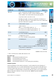
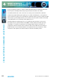

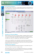

Table Of Contents
- Fig A: Packing List
- Fig B: Power Connections
- Fig C: Mains Lead Table
- Fig 1-1: RB-2S4 Reference Monitor Front Panel
- Fig 1-2: RB-2S10 Reference Monitor Front Panel
- Fig 1-3: Reference Monitor Block Diagram
- Fig 1-4: RM-2S4 Front Panel Controls
- Fig 1-5: RM-2S10 Front Panel Controls
- Fig 1-6: RM-2S4 Source Selector
- Fig 1-7: RM-2S10 Source Selector
- Fig 1-8: RM-2S4 & RM-2S10 Meters
- Fig 1-9: RM-2S4 & RM-2S10 DIPSwitch Settings
- Fig 1-10: Meter Labelling Options
- Fig 1-11: Brightness Control
- Fig 1-13: Balance Control
- Fig 1-12: Phase Meter Display
- Fig 1-14: Status LEDs
- Fig 1-15: RB-2S4 & RB-2S10 Modifier Switches
- Fig 1-16: Reference Monitor RM-2S4 Rear
- Fig 1-17: Reference Monitor RM-2S10 Rear
- Fig 1-18: RM-2S4 & RM-2S10 DIPswitch Settings
- Fig 2-1: RB-4C8 Reference Monitor Front Panel
- Fig 2-2: Reference Monitor Block Diagram
- Fig 2-3: RM-4C8 Front Panel Controls
- Fig 2-4: RM-4C8 Rotary Source Selectors
- Fig 2-5: RM-4C8 Meters
- Fig 2-6: RM-4C8 DIPSwitch Settings
- Fig 2-7: Meter Labelling Options
- Fig 2-8: Brightness Control
- Fig 2-9: Phase Meter Display
- Fig 2-10: Balance Control
- Fig 2-11: Status LEDs
- Fig 2-12: RB-4C8 Modifier Switches
- Fig 2-13: Reference Monitor RM-4C8 Rear
- Fig 3-1: RM-HD1 Expansion Card
- Fig 3-2: RM-HDE1 Expansion Card
- Fig 3-3: Reference Monitor RM-HD(E)1 Block Diagram
- Warranty
- Safety Information
- Installation Information
- Reference Monitors Introduction
- RM-2S4 Reference Monitor, 2 LED meters & 4 stereo
- channel inputs
- RM-2S10 Reference Monitor, 2 LED meters & 10 stereo
- channel inputs
- Technical Specification RM-2S4 & RM-2S10
- RB-4C8 Reference Monitor, 4 LED meters, 8 channel inputs &
- dual selectors
- Technical Specification RM-4C8
- RM-HD1 Reference Monitor HD-SDI Expansion Card &
- RM-HDE1 Reference Monitor HD-SDI & Dolby E Expansion Card
- Technical Specification RM-HD1 & RM-HDE1
- Serial Interface Commands & Responses Protocol

Reference Monitors User Handbook
51
4
SERIAL INTERFACE
COMMANDS & RESPONSES
SERIAL INTERFACE COMMANDS & RESPONSES
Command Description Response
OPT:2,xx Source autodetection for RM-2S10 (see page 6): ACK:
Where: x = 00 selects normal operation (default setting)
x = 01 enables source autoselection (hex values 01 to FF
accepted and have same eect as 01).
The SRQ: query will correctly report the bank currently in use.
The UID: query will report a single bank of 10 sources rather than
two when autoselect is enabled.
SER: - Serial Number request SER:nnnnnn
SRQ: - Status request SRQ:BxLyRz
Where: x = current bank number (1…n).
y = current source number for LH speaker (1…n).
z = current source number for RH speaker (1…n).
SS1:nn - Set Left-hand Source ACK:
nn = Source number, starting with 01.
SS2:nn - Set Right-hand Source ACK:
nn = Source number, starting with 01.
UID:* - Unit ID Request UID:RM4:V11yyyy
or UID:RM-2S4-xxxxxx
or UID:RM-2S10-xxxxxx
or UID:RM-4C8-xxxxxx
or UID:RM4/A (bootloader)
Where: x = number of sources available in each of banks 1-6
y = dependent on Banks tted.
VER:* - Firmware Version Request VER:n.nn
or BOOT:n.nn (bootloader)
* = these commands also valid in Bootloader mode.
Error Messages
ERR:01 - returned if Command Not Found.
ERR:02 - returned if Missing Parameter.
ERR:04 - returned if Parameter out of range.
ERR:08 - returned if Checksum Error occurs during reprogramming.
Firmware Updates
The internal rmware of the Reference Monitors can be updated to take advantage of
newly added features. It is recommended that this be done using the Sonifex SCi remote
control package, but it may also be done using the command protocol provided and the
“Send Text File” (or similar) facility in text-based terminal programs such as Hyperterminal.
When prompted for a lename, locate and select the .DWN le provided with the
rmware update.