
Manual
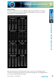
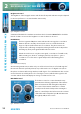
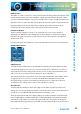
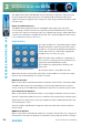
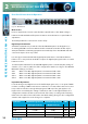
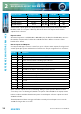

Table Of Contents
- Fig A: Packing List
- Fig B: Power Connections
- Fig C: Mains Lead Table
- Fig 1-1: RB-2S4 Reference Monitor Front Panel
- Fig 1-2: RB-2S10 Reference Monitor Front Panel
- Fig 1-3: Reference Monitor Block Diagram
- Fig 1-4: RM-2S4 Front Panel Controls
- Fig 1-5: RM-2S10 Front Panel Controls
- Fig 1-6: RM-2S4 Source Selector
- Fig 1-7: RM-2S10 Source Selector
- Fig 1-8: RM-2S4 & RM-2S10 Meters
- Fig 1-9: RM-2S4 & RM-2S10 DIPSwitch Settings
- Fig 1-10: Meter Labelling Options
- Fig 1-11: Brightness Control
- Fig 1-13: Balance Control
- Fig 1-12: Phase Meter Display
- Fig 1-14: Status LEDs
- Fig 1-15: RB-2S4 & RB-2S10 Modifier Switches
- Fig 1-16: Reference Monitor RM-2S4 Rear
- Fig 1-17: Reference Monitor RM-2S10 Rear
- Fig 1-18: RM-2S4 & RM-2S10 DIPswitch Settings
- Fig 2-1: RB-4C8 Reference Monitor Front Panel
- Fig 2-2: Reference Monitor Block Diagram
- Fig 2-3: RM-4C8 Front Panel Controls
- Fig 2-4: RM-4C8 Rotary Source Selectors
- Fig 2-5: RM-4C8 Meters
- Fig 2-6: RM-4C8 DIPSwitch Settings
- Fig 2-7: Meter Labelling Options
- Fig 2-8: Brightness Control
- Fig 2-9: Phase Meter Display
- Fig 2-10: Balance Control
- Fig 2-11: Status LEDs
- Fig 2-12: RB-4C8 Modifier Switches
- Fig 2-13: Reference Monitor RM-4C8 Rear
- Fig 3-1: RM-HD1 Expansion Card
- Fig 3-2: RM-HDE1 Expansion Card
- Fig 3-3: Reference Monitor RM-HD(E)1 Block Diagram
- Warranty
- Safety Information
- Installation Information
- Reference Monitors Introduction
- RM-2S4 Reference Monitor, 2 LED meters & 4 stereo
- channel inputs
- RM-2S10 Reference Monitor, 2 LED meters & 10 stereo
- channel inputs
- Technical Specification RM-2S4 & RM-2S10
- RB-4C8 Reference Monitor, 4 LED meters, 8 channel inputs &
- dual selectors
- Technical Specification RM-4C8
- RM-HD1 Reference Monitor HD-SDI Expansion Card &
- RM-HDE1 Reference Monitor HD-SDI & Dolby E Expansion Card
- Technical Specification RM-HD1 & RM-HDE1
- Serial Interface Commands & Responses Protocol

38
Reference Monitors User Handbook
REFERENCE MONITORS RM-4C8
REFERENCE MONITORS RM-4C8
2
Output Format Output Level SW1 & 2 SW3 & 4 SW5
Analogue Variable Both ON Both OFF OFF
Analogue Fixed Both ON Both OFF ON
AES/EBU Digital Variable Both OFF Both ON OFF
AES/EBU Digital Fixed Both OFF Both ON ON
The line-level output signals are always aected by the setting of the front-panel audio
Modiers, with one exception - DIM only aects the line-level outputs when Variable
output level is selected.
Expansion Port
An internal expansion card (RM-HD1 or RM-HDE1) may be tted to the RM-4C8 to increase
the number of inputs and/or add to the available functions. Refer to Section 3 of this
handbook for details.
Remote Inputs and Outputs
A 15-way male D-type connector carries four open-collector status outputs, four logic-level
control inputs plus power and data lines for future use. The pin assignations are as follows:
Pin No. I/O Function
1 O Audio underlevel/fail alarm – latching open collector
9 I MUTE input – pull low to activate
2 O Audio overlevel alarm – latching open collector
10 I DIM input – pull low to activate
3 O Sustained phase error alarm – latching open collector
11 I Alarm Reset – pull low to activate
4 O AES/EBU lock output – non-latching open collector
12 I Not used
5 I Volume control voltage for future use
13 I Balance control voltage for future use
6 O Fused power for desktop remote control panel
14 - Ground
7 O Serial data transmit for future use
15 I Serial data receive for future use
8 O Serial clock for future use
Open-collector outputs are low (conducting) during normal operation. When an alarm
occurs they cease conducting and, with the exception of the AES/EBU lock output, remain
in that condition until the Alarm Reset input is asserted. Open-collector outputs are rated
at 50mA and 30V.
The Audio Overlevel alarm is triggered if either currently selected input Source exceeds
+12dBu for longer than 5 seconds.