
Manual
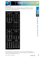
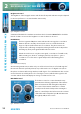
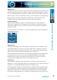
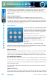
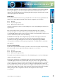

Table Of Contents
- Fig A: Packing List
- Fig B: Power Connections
- Fig C: Mains Lead Table
- Fig 1-1: RB-2S4 Reference Monitor Front Panel
- Fig 1-2: RB-2S10 Reference Monitor Front Panel
- Fig 1-3: Reference Monitor Block Diagram
- Fig 1-4: RM-2S4 Front Panel Controls
- Fig 1-5: RM-2S10 Front Panel Controls
- Fig 1-6: RM-2S4 Source Selector
- Fig 1-7: RM-2S10 Source Selector
- Fig 1-8: RM-2S4 & RM-2S10 Meters
- Fig 1-9: RM-2S4 & RM-2S10 DIPSwitch Settings
- Fig 1-10: Meter Labelling Options
- Fig 1-11: Brightness Control
- Fig 1-13: Balance Control
- Fig 1-12: Phase Meter Display
- Fig 1-14: Status LEDs
- Fig 1-15: RB-2S4 & RB-2S10 Modifier Switches
- Fig 1-16: Reference Monitor RM-2S4 Rear
- Fig 1-17: Reference Monitor RM-2S10 Rear
- Fig 1-18: RM-2S4 & RM-2S10 DIPswitch Settings
- Fig 2-1: RB-4C8 Reference Monitor Front Panel
- Fig 2-2: Reference Monitor Block Diagram
- Fig 2-3: RM-4C8 Front Panel Controls
- Fig 2-4: RM-4C8 Rotary Source Selectors
- Fig 2-5: RM-4C8 Meters
- Fig 2-6: RM-4C8 DIPSwitch Settings
- Fig 2-7: Meter Labelling Options
- Fig 2-8: Brightness Control
- Fig 2-9: Phase Meter Display
- Fig 2-10: Balance Control
- Fig 2-11: Status LEDs
- Fig 2-12: RB-4C8 Modifier Switches
- Fig 2-13: Reference Monitor RM-4C8 Rear
- Fig 3-1: RM-HD1 Expansion Card
- Fig 3-2: RM-HDE1 Expansion Card
- Fig 3-3: Reference Monitor RM-HD(E)1 Block Diagram
- Warranty
- Safety Information
- Installation Information
- Reference Monitors Introduction
- RM-2S4 Reference Monitor, 2 LED meters & 4 stereo
- channel inputs
- RM-2S10 Reference Monitor, 2 LED meters & 10 stereo
- channel inputs
- Technical Specification RM-2S4 & RM-2S10
- RB-4C8 Reference Monitor, 4 LED meters, 8 channel inputs &
- dual selectors
- Technical Specification RM-4C8
- RM-HD1 Reference Monitor HD-SDI Expansion Card &
- RM-HDE1 Reference Monitor HD-SDI & Dolby E Expansion Card
- Technical Specification RM-HD1 & RM-HDE1
- Serial Interface Commands & Responses Protocol

Reference Monitors User Handbook
33
REFERENCE MONITORS RM-4C8
REFERENCE MONITORS RM-4C8
2
LEVEL Control
The LEVEL, or volume, control is a rotary potentiometer allowing volume adjustment of the
internal loudspeaker system, the headphone output and optionally the line level outputs
(see Line Level Audio Outputs on page 37). A usable control range of 36dB is provided, and
with the volume control in the fully anti-clockwise position the signal is completely muted.
High input signal levels and/or high volume settings may result in activation of the
loudspeaker protection limiter (refer to the Limiter section of this manual).
Headphone Output
The front panel headphone output is a ¼” (6.35mm) stereo jack socket capable of
delivering over 80mW into 32Ω - 600Ω professional headphones at full volume. Higher
impedance headphones may be used at reduced levels. Lower impedance headphones
should not be used.
Inserting a plug into the headphone socket automatically mutes the internal loudspeakers.
STATUS LED Indicators
Fig 2-11: Status LEDs
LIMIT indicator
The LIMIT indicator illuminates to show that the loudspeaker protection limiter has been
activated. This happens in response to excessive volume levels – which are a product of
input signal level and the setting of the volume control – being requested from the unit
and is necessary to prevent permanent damage to the loudspeakers.
The protection limiter is a fast-attack, slow-release type. Brief ashes of the LIMIT indicator
on signal peaks are not cause for concern, but signicant illumination indicates that
the signal is being compressed and that reproduction may be compromised. In those
circumstances the setting of the volume control should be reduced.
CLIP indicator
The CLIP indicator illuminates when the signal level of either currently selected Source
(taking into account any input gain applied – refer to the Inputs section of this manual) has
exceeded or come within 0.5dB of that at which hard clipping occurs.
Analogue input signals will cause clipping if they exceed the maximum acceptable input
level (+18dBu with no additional input gain, reducing by 6dB for every 6dB of input gain
applied). The only solution is to reduce the input level and/or the amount of input gain
being applied; allowing clipping to persist will irreversibly degrade the audio performance.