
Manual
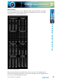
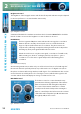
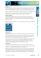
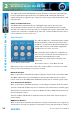
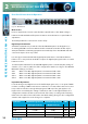
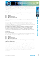
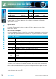

Table Of Contents
- Fig A: Packing List
- Fig B: Power Connections
- Fig C: Mains Lead Table
- Fig 1-1: RB-2S4 Reference Monitor Front Panel
- Fig 1-2: RB-2S10 Reference Monitor Front Panel
- Fig 1-3: Reference Monitor Block Diagram
- Fig 1-4: RM-2S4 Front Panel Controls
- Fig 1-5: RM-2S10 Front Panel Controls
- Fig 1-6: RM-2S4 Source Selector
- Fig 1-7: RM-2S10 Source Selector
- Fig 1-8: RM-2S4 & RM-2S10 Meters
- Fig 1-9: RM-2S4 & RM-2S10 DIPSwitch Settings
- Fig 1-10: Meter Labelling Options
- Fig 1-11: Brightness Control
- Fig 1-13: Balance Control
- Fig 1-12: Phase Meter Display
- Fig 1-14: Status LEDs
- Fig 1-15: RB-2S4 & RB-2S10 Modifier Switches
- Fig 1-16: Reference Monitor RM-2S4 Rear
- Fig 1-17: Reference Monitor RM-2S10 Rear
- Fig 1-18: RM-2S4 & RM-2S10 DIPswitch Settings
- Fig 2-1: RB-4C8 Reference Monitor Front Panel
- Fig 2-2: Reference Monitor Block Diagram
- Fig 2-3: RM-4C8 Front Panel Controls
- Fig 2-4: RM-4C8 Rotary Source Selectors
- Fig 2-5: RM-4C8 Meters
- Fig 2-6: RM-4C8 DIPSwitch Settings
- Fig 2-7: Meter Labelling Options
- Fig 2-8: Brightness Control
- Fig 2-9: Phase Meter Display
- Fig 2-10: Balance Control
- Fig 2-11: Status LEDs
- Fig 2-12: RB-4C8 Modifier Switches
- Fig 2-13: Reference Monitor RM-4C8 Rear
- Fig 3-1: RM-HD1 Expansion Card
- Fig 3-2: RM-HDE1 Expansion Card
- Fig 3-3: Reference Monitor RM-HD(E)1 Block Diagram
- Warranty
- Safety Information
- Installation Information
- Reference Monitors Introduction
- RM-2S4 Reference Monitor, 2 LED meters & 4 stereo
- channel inputs
- RM-2S10 Reference Monitor, 2 LED meters & 10 stereo
- channel inputs
- Technical Specification RM-2S4 & RM-2S10
- RB-4C8 Reference Monitor, 4 LED meters, 8 channel inputs &
- dual selectors
- Technical Specification RM-4C8
- RM-HD1 Reference Monitor HD-SDI Expansion Card &
- RM-HDE1 Reference Monitor HD-SDI & Dolby E Expansion Card
- Technical Specification RM-HD1 & RM-HDE1
- Serial Interface Commands & Responses Protocol

32
Reference Monitors User Handbook
REFERENCE MONITORS RM-4C8
REFERENCE MONITORS RM-4C8
2
Brightness Control
The brightness of the bargraph meters and all other front panel indicators may be adjusted
to suit user preference or to match similar units nearby.
Fig 2-8: Brightness Control
A miniature at-bladed screwdriver inserted into the hole marked BRIGHTNESS should be
turned clockwise to increase the brightness or anti-clockwise to decrease.
PHASE Meter
The ve-segment LED phase meter indicates the average phase correlation
between the two currently selected audio Sources. It is labelled in both
degrees of phase shift and amount of correlation. The phase meter is an
“output” meter, reecting exactly what is being heard from the loudspeakers
including any front panel signal Modiers that are active.
If both selected Sources carry the same signal, a correlation of 1.0 will result,
while inverting one channel – making it perfectly out of phase – gives a
correlation of -1.0. True stereo signals will produce a uctuating phase
correlation.
Fig 2-9: Phase Meter Display
An interesting situation arises when only one of the selected Sources is fed with signal. If
the unused channel is perfectly silent (as is possible in the case of a digital source) then
the phase correlation will average 0.0, but a small degree of crosstalk between the used an
unused channels (as is likely in the case of analogue sources) will allow the signal to self-
correlate and the meter will display an average correlation nearer 1.0.
BALANCE Control
The balance control is a centre-detented rotary
potentiometer allowing adjustment of the relative
balance between the left and right loudspeakers.
The control characteristic maintains a constant
overall power from the loudspeakers. turning the
balance control fully to the left increases the volume
of the left-hand loudspeaker by 6dB and attenuates
the right by 6dB, and vice-versa.
Fig 2-10: Balance Control