
Manual
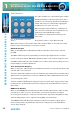
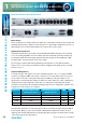
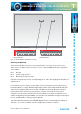
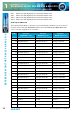
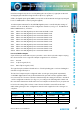
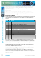
Table Of Contents
- Fig A: Packing List
- Fig B: Power Connections
- Fig C: Mains Lead Table
- Fig 1-1: RB-2S4 Reference Monitor Front Panel
- Fig 1-2: RB-2S10 Reference Monitor Front Panel
- Fig 1-3: Reference Monitor Block Diagram
- Fig 1-4: RM-2S4 Front Panel Controls
- Fig 1-5: RM-2S10 Front Panel Controls
- Fig 1-6: RM-2S4 Source Selector
- Fig 1-7: RM-2S10 Source Selector
- Fig 1-8: RM-2S4 & RM-2S10 Meters
- Fig 1-9: RM-2S4 & RM-2S10 DIPSwitch Settings
- Fig 1-10: Meter Labelling Options
- Fig 1-11: Brightness Control
- Fig 1-13: Balance Control
- Fig 1-12: Phase Meter Display
- Fig 1-14: Status LEDs
- Fig 1-15: RB-2S4 & RB-2S10 Modifier Switches
- Fig 1-16: Reference Monitor RM-2S4 Rear
- Fig 1-17: Reference Monitor RM-2S10 Rear
- Fig 1-18: RM-2S4 & RM-2S10 DIPswitch Settings
- Fig 2-1: RB-4C8 Reference Monitor Front Panel
- Fig 2-2: Reference Monitor Block Diagram
- Fig 2-3: RM-4C8 Front Panel Controls
- Fig 2-4: RM-4C8 Rotary Source Selectors
- Fig 2-5: RM-4C8 Meters
- Fig 2-6: RM-4C8 DIPSwitch Settings
- Fig 2-7: Meter Labelling Options
- Fig 2-8: Brightness Control
- Fig 2-9: Phase Meter Display
- Fig 2-10: Balance Control
- Fig 2-11: Status LEDs
- Fig 2-12: RB-4C8 Modifier Switches
- Fig 2-13: Reference Monitor RM-4C8 Rear
- Fig 3-1: RM-HD1 Expansion Card
- Fig 3-2: RM-HDE1 Expansion Card
- Fig 3-3: Reference Monitor RM-HD(E)1 Block Diagram
- Warranty
- Safety Information
- Installation Information
- Reference Monitors Introduction
- RM-2S4 Reference Monitor, 2 LED meters & 4 stereo
- channel inputs
- RM-2S10 Reference Monitor, 2 LED meters & 10 stereo
- channel inputs
- Technical Specification RM-2S4 & RM-2S10
- RB-4C8 Reference Monitor, 4 LED meters, 8 channel inputs &
- dual selectors
- Technical Specification RM-4C8
- RM-HD1 Reference Monitor HD-SDI Expansion Card &
- RM-HDE1 Reference Monitor HD-SDI & Dolby E Expansion Card
- Technical Specification RM-HD1 & RM-HDE1
- Serial Interface Commands & Responses Protocol

Reference Monitors User Handbook
17
REFERENCE MONITORS RM-2S4 & RM-2S10
REFERENCE MONITORS RM-2S4 & RM-2S10
1
Unbalanced signals may also be used by linking the out-of-phase (-) signal pin to Ground
and applying the unbalanced signal to the in-phase (+) signal pin.
A full-scale digital input signal (0dBFS) corresponds to the maximum analogue input signal
level of +18dBu (with no extra input gain applied).
110 ohm input termination for the AES/EBU digital inputs is controlled by the settings of
switches 1 to 10 on the Block 2 of the conguration switches (see Fig 1-17: The RM-2S4 &
RM-2S10 DIPswitches), as follows:
SW1: When set to ON, digital input 10 is terminated with 110 Ω.
SW2: When set to ON, digital input 9 is terminated with 110 Ω.
SW3: When set to ON, digital input 8 is terminated with 110 Ω.
SW4: When set to ON, digital input 7 is terminated with 110 Ω.
SW5: When set to ON, digital input 6 is terminated with 110 Ω.
SW6: When set to ON, digital input 5 is terminated with 110 Ω.
SW7: When set to ON, digital input 4 is terminated with 110 Ω.
SW8: When set to ON, digital input 3 is terminated with 110 Ω.
SW9: When set to ON, digital input 2 is terminated with 110 Ω.
SW10: When set to ON, digital input 1 is terminated with 110 Ω.
Line Level Audio Outputs
A pair of three-pin male XLR connectors provides a stereo line-level audio output carrying
the selected audio Source signal. The XLR pin assignations are as follows:
Pin 1: Ground
Pin 2: In-phase signal (“hot”)
Pin 3: Out-of-phase signal (“cold”)
The signals may be unbalanced without loss of level by linking pins 1 and 3 and taking the
unbalanced signal from pin 2.
The line-level outputs may be congured either as analogue (using both output XLRs)
or AES/EBU digital (attach to the left-hand XLR of the pair and leave the right-hand XLR
unconnected). The selection of format is determined by the setting of switches 1-4 in Block
1 of the conguration switches (see Fig 1-17), according to the following table. Switch 5 in
the same block determines whether the line-level outputs are xed in level or proportional
in level to the setting of the volume control. Power should be removed from the unit
while making changes to the conguration switches and reapplied once the changes are
complete.
Output Format Output Level SW1 & 2 SW3 & 4 SW5
Analogue Variable Both ON Both OFF OFF
Analogue Fixed Both ON Both OFF ON
AES/EBU Digital Variable Both OFF Both ON OFF
AES/EBU Digital Fixed Both OFF Both ON ON