
Manual
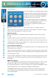
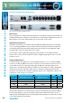
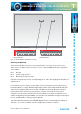
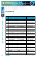
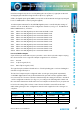
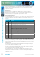
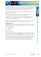
Table Of Contents
- Fig A: Packing List
- Fig B: Power Connections
- Fig C: Mains Lead Table
- Fig 1-1: RB-2S4 Reference Monitor Front Panel
- Fig 1-2: RB-2S10 Reference Monitor Front Panel
- Fig 1-3: Reference Monitor Block Diagram
- Fig 1-4: RM-2S4 Front Panel Controls
- Fig 1-5: RM-2S10 Front Panel Controls
- Fig 1-6: RM-2S4 Source Selector
- Fig 1-7: RM-2S10 Source Selector
- Fig 1-8: RM-2S4 & RM-2S10 Meters
- Fig 1-9: RM-2S4 & RM-2S10 DIPSwitch Settings
- Fig 1-10: Meter Labelling Options
- Fig 1-11: Brightness Control
- Fig 1-13: Balance Control
- Fig 1-12: Phase Meter Display
- Fig 1-14: Status LEDs
- Fig 1-15: RB-2S4 & RB-2S10 Modifier Switches
- Fig 1-16: Reference Monitor RM-2S4 Rear
- Fig 1-17: Reference Monitor RM-2S10 Rear
- Fig 1-18: RM-2S4 & RM-2S10 DIPswitch Settings
- Fig 2-1: RB-4C8 Reference Monitor Front Panel
- Fig 2-2: Reference Monitor Block Diagram
- Fig 2-3: RM-4C8 Front Panel Controls
- Fig 2-4: RM-4C8 Rotary Source Selectors
- Fig 2-5: RM-4C8 Meters
- Fig 2-6: RM-4C8 DIPSwitch Settings
- Fig 2-7: Meter Labelling Options
- Fig 2-8: Brightness Control
- Fig 2-9: Phase Meter Display
- Fig 2-10: Balance Control
- Fig 2-11: Status LEDs
- Fig 2-12: RB-4C8 Modifier Switches
- Fig 2-13: Reference Monitor RM-4C8 Rear
- Fig 3-1: RM-HD1 Expansion Card
- Fig 3-2: RM-HDE1 Expansion Card
- Fig 3-3: Reference Monitor RM-HD(E)1 Block Diagram
- Warranty
- Safety Information
- Installation Information
- Reference Monitors Introduction
- RM-2S4 Reference Monitor, 2 LED meters & 4 stereo
- channel inputs
- RM-2S10 Reference Monitor, 2 LED meters & 10 stereo
- channel inputs
- Technical Specification RM-2S4 & RM-2S10
- RB-4C8 Reference Monitor, 4 LED meters, 8 channel inputs &
- dual selectors
- Technical Specification RM-4C8
- RM-HD1 Reference Monitor HD-SDI Expansion Card &
- RM-HDE1 Reference Monitor HD-SDI & Dolby E Expansion Card
- Technical Specification RM-HD1 & RM-HDE1
- Serial Interface Commands & Responses Protocol

Reference Monitors User Handbook
15
REFERENCE MONITORS RM-2S4 & RM-2S10
REFERENCE MONITORS RM-2S4 & RM-2S10
1
Fig 1-18: RM-2S4 & RM-2S10 DIPswitch Settings
Audio Inputs (RM-2S4)
Three-pin female XLR connectors are provided for the connection of up to four stereo
audio sources. Together, these four stereo sources comprise BANK A. The pin assignations
are as follows:
Pin 1: Ground
Pin 2: In-phase signal (“hot”)
Pin 3: Out-of-phase signal (“cold”)
Unbalanced signals may also be used by linking pins 1 and 3 and applying the unbalanced
signal to pin 2.
Each of the four source inputs accepts either a pair of analogue line-level signals (using
both input XLRs) or a single AES/EBU digital signal (attach to the left-hand XLR of the pair
and leave the right-hand XLR unconnected). The RM-2S4 automatically detects digital
input signals and seamlessly presents them for selection in exactly the same way as
analogue ones; the inputs may therefore be any mixture of analogue and digital sources.
A full-scale digital input signal (0dBFS) corresponds to the maximum analogue input signal
level of +18dBu (with no extra input gain applied).
110 ohm input termination for the AES/EBU digital inputs is controlled by the settings of
switches 1, 2, 11 and 12 on Block 2 of the conguration switches, as follows:
1
ON DIP
2 3 4 5 6 7 8 9 10 11 12 1
ON DIP
2 3 4 5 6 7 8 9 10 11 12
1
ON DIP
2 3 4 5 6 7 8 9
10 11 12 1
ON DIP
2 3 4 5 6 7 8 9
10 11 12
Reference Monitor underside
DIPSwitch Block 1 DIPSwitch Block 2