
Manual
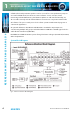
Table Of Contents
- Fig A: Packing List
- Fig B: Power Connections
- Fig C: Mains Lead Table
- Fig 1-1: RB-2S4 Reference Monitor Front Panel
- Fig 1-2: RB-2S10 Reference Monitor Front Panel
- Fig 1-3: Reference Monitor Block Diagram
- Fig 1-4: RM-2S4 Front Panel Controls
- Fig 1-5: RM-2S10 Front Panel Controls
- Fig 1-6: RM-2S4 Source Selector
- Fig 1-7: RM-2S10 Source Selector
- Fig 1-8: RM-2S4 & RM-2S10 Meters
- Fig 1-9: RM-2S4 & RM-2S10 DIPSwitch Settings
- Fig 1-10: Meter Labelling Options
- Fig 1-11: Brightness Control
- Fig 1-13: Balance Control
- Fig 1-12: Phase Meter Display
- Fig 1-14: Status LEDs
- Fig 1-15: RB-2S4 & RB-2S10 Modifier Switches
- Fig 1-16: Reference Monitor RM-2S4 Rear
- Fig 1-17: Reference Monitor RM-2S10 Rear
- Fig 1-18: RM-2S4 & RM-2S10 DIPswitch Settings
- Fig 2-1: RB-4C8 Reference Monitor Front Panel
- Fig 2-2: Reference Monitor Block Diagram
- Fig 2-3: RM-4C8 Front Panel Controls
- Fig 2-4: RM-4C8 Rotary Source Selectors
- Fig 2-5: RM-4C8 Meters
- Fig 2-6: RM-4C8 DIPSwitch Settings
- Fig 2-7: Meter Labelling Options
- Fig 2-8: Brightness Control
- Fig 2-9: Phase Meter Display
- Fig 2-10: Balance Control
- Fig 2-11: Status LEDs
- Fig 2-12: RB-4C8 Modifier Switches
- Fig 2-13: Reference Monitor RM-4C8 Rear
- Fig 3-1: RM-HD1 Expansion Card
- Fig 3-2: RM-HDE1 Expansion Card
- Fig 3-3: Reference Monitor RM-HD(E)1 Block Diagram
- Warranty
- Safety Information
- Installation Information
- Reference Monitors Introduction
- RM-2S4 Reference Monitor, 2 LED meters & 4 stereo
- channel inputs
- RM-2S10 Reference Monitor, 2 LED meters & 10 stereo
- channel inputs
- Technical Specification RM-2S4 & RM-2S10
- RB-4C8 Reference Monitor, 4 LED meters, 8 channel inputs &
- dual selectors
- Technical Specification RM-4C8
- RM-HD1 Reference Monitor HD-SDI Expansion Card &
- RM-HDE1 Reference Monitor HD-SDI & Dolby E Expansion Card
- Technical Specification RM-HD1 & RM-HDE1
- Serial Interface Commands & Responses Protocol

6
Reference Monitors User Handbook
REFERENCE MONITORS RM-2S4 & RM-2S10
REFERENCE MONITORS RM-2S4 & RM-2S10
1
than four (RM-2S4) or ten (RM-2S10) Sources, it will not be possible to select
unimplemented Sources.
When mains power is removed, the currently selected Source is stored in non-volatile
memory and recalled instantly once power is restored.
Auto-Selection of Inputs
As standard, the RM-2S4 has auto-selection of the inputs, i.e. whichever analogue or digital
signal is connected to the input will be used. There is also an option (in the serial settings)
for the RM-2S10 to have auto-selection of it’s separate ten analogue inputs in Bank ANA
and ten digital inputs in Bank DIG. For users with a smaller number of mixed analogue and
digital sources, the auto-selection allows the unit to switch automatically between the
analogue and digital banks according to what is connected.
For the RM-2S10, with auto-selection enabled, both the Bank ANA and Bank DIG LEDs are
illuminated (expansion banks can still be selected as normal, if tted). If the current source
selection points to a valid digital input then the digital input will be selected. If it does not,
the similarly numbered analogue source will be used. If both are present then the digital
input takes precedence (hence auto-selection is only useful for a maximum of ten sources).
The analogue and digital presence indications are combined (ORed) and displayed
simultaneously.
Bank Selector
Pressing the Source selector knob inwards steps sequentially through all available input
Banks (groups of stereo inputs). Each press ashes the selected Bank LED and moves the
selected Bank onwards by one step. Once the last available Bank is selected, a further press
returns the selection to the rst available Bank. The currently selected Bank is indicated by
illumination of the corresponding Bank LED.
The currently selected Bank may also be changed via the remote control ports (see the
appropriate sections of this manual), and such changes will also be reected by the
Bank LEDs.
On the RM-2S4, BANK A corresponds to the four autoselecting (analogue or digital) stereo
inputs found on the rear panel, and further Banks become available with the addition of
optional expansion cards.
On the RM-2S10, separate Banks are provided for analogue (BANK ANA) and digital (BANK
DIG) sources – a total of twenty stereo sources may be attached if both Banks are fully
utilised. Further Banks become available with the addition of optional expansion cards. It is
not possible to select Banks which are not tted.
When mains power is removed, the currently selected Bank is stored in non-volatile
memory and recalled instantly once power is restored.