
Manual
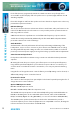
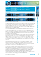
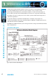
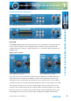
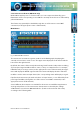
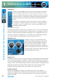
Table Of Contents
- Fig A: Packing List
- Fig B: Power Connections
- Fig C: Mains Lead Table
- Fig 1-1: RB-2S4 Reference Monitor Front Panel
- Fig 1-2: RB-2S10 Reference Monitor Front Panel
- Fig 1-3: Reference Monitor Block Diagram
- Fig 1-4: RM-2S4 Front Panel Controls
- Fig 1-5: RM-2S10 Front Panel Controls
- Fig 1-6: RM-2S4 Source Selector
- Fig 1-7: RM-2S10 Source Selector
- Fig 1-8: RM-2S4 & RM-2S10 Meters
- Fig 1-9: RM-2S4 & RM-2S10 DIPSwitch Settings
- Fig 1-10: Meter Labelling Options
- Fig 1-11: Brightness Control
- Fig 1-13: Balance Control
- Fig 1-12: Phase Meter Display
- Fig 1-14: Status LEDs
- Fig 1-15: RB-2S4 & RB-2S10 Modifier Switches
- Fig 1-16: Reference Monitor RM-2S4 Rear
- Fig 1-17: Reference Monitor RM-2S10 Rear
- Fig 1-18: RM-2S4 & RM-2S10 DIPswitch Settings
- Fig 2-1: RB-4C8 Reference Monitor Front Panel
- Fig 2-2: Reference Monitor Block Diagram
- Fig 2-3: RM-4C8 Front Panel Controls
- Fig 2-4: RM-4C8 Rotary Source Selectors
- Fig 2-5: RM-4C8 Meters
- Fig 2-6: RM-4C8 DIPSwitch Settings
- Fig 2-7: Meter Labelling Options
- Fig 2-8: Brightness Control
- Fig 2-9: Phase Meter Display
- Fig 2-10: Balance Control
- Fig 2-11: Status LEDs
- Fig 2-12: RB-4C8 Modifier Switches
- Fig 2-13: Reference Monitor RM-4C8 Rear
- Fig 3-1: RM-HD1 Expansion Card
- Fig 3-2: RM-HDE1 Expansion Card
- Fig 3-3: Reference Monitor RM-HD(E)1 Block Diagram
- Warranty
- Safety Information
- Installation Information
- Reference Monitors Introduction
- RM-2S4 Reference Monitor, 2 LED meters & 4 stereo
- channel inputs
- RM-2S10 Reference Monitor, 2 LED meters & 10 stereo
- channel inputs
- Technical Specification RM-2S4 & RM-2S10
- RB-4C8 Reference Monitor, 4 LED meters, 8 channel inputs &
- dual selectors
- Technical Specification RM-4C8
- RM-HD1 Reference Monitor HD-SDI Expansion Card &
- RM-HDE1 Reference Monitor HD-SDI & Dolby E Expansion Card
- Technical Specification RM-HD1 & RM-HDE1
- Serial Interface Commands & Responses Protocol

Reference Monitors User Handbook
2
REFERENCE MONITORS
REFERENCE MONITORS
Each of the drivers is magnetically shielded so that the monitors are perfectly safe to
use near CRTs and TFT displays and each speaker uses a separate, highly ecient class-D
switching amplier.
Even cable lengths to and from the speaker enclosures have been kept short to reduce any
potential microphonic induction.
DSP Based Design
The use of a modern electronic architecture allows a much better audio performance to be
realised. The DSP-based, 3rd-order active crossover provides perfect separation between
mid-range and bass sounds.
A DSP-based electronic equalisation is used to atten the frequency response and also
enables the 5 band parametric EQ. Additionally, the fast-attack DSP loudspeaker limiter
protects the drivers from overload damage.
Audio Modiers
Six illuminated soft-touch pushbuttons allow front panel muting and dimming of the
loudspeakers., stereo-to-mono conversion., phase inversion and Middle+Side encoding/
decoding with all front panel settings stored in non-volatile memory which is recalled at
power-up. A universal power supply ensures global voltage operation without adjustment.
5 Band Parametric Equalisation
Each product in the Reference Monitor range contains an embedded 5 band parametric
equaliser.
On testing the units, they are set up to give a at response across the quoted frequency
range, but the parametric EQ allows you to alter the response either to account for poor
acoustics in the room that the monitor is mounted in, or to suit your particular listening
tastes.
Using the free of charge SCi remote control software, preset EQ settings can be selected, or
dierent EQ settings can be created and stored.
Front Panel Lock-Out
The controls on the front panel can optionally be locked out if required by using the free of
charge SCi remote control software.
Optional HD Expansion Cards
RM-HD1 HD-SDI expansion card &
RM-HDE1 HD-SDI & Dolby E Decoder expansion card
The HD-SDI video input expansion cards allow multiple AES groups embedded within an
HD-SDI or SD-SDI signal to be de-embedded and monitored, either as linear PCM with
Dolby E and Dolby Digital decoding (RM-HD1E), or as non-encoded linear PCM (RM-HD1).
The HD-SDI input is equalised, internally reclocked and re-transmitted to provide a
reclocked output to pass to external equipment via an output BNC connector, allowing the
reference monitor to be inserted into an HD-SDI chain.