
Manual
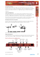
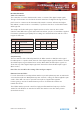
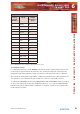
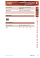

Table Of Contents
- Warranty
- Safety Information
- 1 RB-SS10 10 Way Stereo Analogue Source Selector/Mixer
- Technical Specifications RB-SS10
- 2 RB-DSS10 10 Way Stereo Digital Source Selector
- Technical Specifications RB-DSS10
- 3 RB-PMX4 10 Input, 4 Output Analogue Preset Mixer
- Technical Specifications RB-PMX4
- 4 RB-SSML1 Mic/Line Source Selector with Compressor Limiter
- Technical Specifications
- 5 RB-MA1 Single & RB-MA2 Dual Microphone Amplifiers
- Technical Specifications RB-MA1 & RB-MA2
- 6 RB-DMA2 Dual Digital Microphone Amplifier
- Technical Specifications RB-DMA2
- 7 RB-ML2 Stereo Microphone & Line Level Limiter
- Technical Specifications RB-ML2
- 8 RB-SL2 Twin Mono, or Stereo, Limiter
- Technical Specifications RB-SL2
- 9 RB-SM1 Single & RB-SM2 Dual Stereo To Mono Converter
- Technical Specifications RB-SM1 & RB-SM2
- 10 RB-LC3 3 Way Light/Power Controller
- Technical Specifications RB-LC3
- 11 RB-MM1 Mix Minus Generator
- Technical Specification RB-MM1
- Fig A: Packing List.
- Fig B: Fuse Rating Table.
- Fig C: Mains Cable Wire Colours
- Fig D: Mains Lead Table.
- Fig E: RB-RK1Small Redbox Front Rack-mount Kit .
- Fig F: RB-RK2 Small Redbox Rear Rack-mount Kit.
- Fig G: RB-RK3 Large Redbox Rear Rack-mount Kit.
- Fig 1-1: RB-SS10 Front Panel.
- Fig 1-2: RB-SS10 System Block Diagram.
- Fig 1-3: RB-SS10 Front Panel.
- Fig 1-4: RB-SS10 Rear Panel.
- Fig 1-5: Analogue Audio Inputs Pin Connections
- Fig 1-6: Remote Start Pin Connections.
- Fig 1-7: Connection Example.
- Fig 1-8: Remote Select/Switch Input Connections.
- Fig 1-9: Connection Example.
- Fig 1-10: Status Output Pin Connections.
- Fig 1-11: Connection Example.
- Fig 2-1: RB-DSS10 Front Panel.
- Fig 2-2: RB-DSS10 System Block Diagram.
- Fig 2-3: RB-DSS10 Front Panel.
- Fig 2-4: RB-DSS10 Rear Panel.
- Fig 2-5: Digital Audio Inputs and S/PDIF Output Pin Connections.
- Fig 2-6: Remote Start Pin Connections.
- Fig 2-7: Connection Example.
- Fig 2-8: Remote Select/Switch Input Connections.
- Fig 2-9: Connection Example.
- Fig 2-10: Status Output Pin Connections.
- Fig 2-11: Connection Example.
- Fig 3-1: RB-PMX4 Front Panel .
- Fig 3-2: RB-PMX4 Block Diagram.
- Fig 3-3: RB-PMX4 Rear Panel.
- Fig 3-4: RB-PMX4 Front Panel Controls.
- Fig 4-1: RB-SSML1 Front Panel.
- Fig 4-2: RB-SSML1 Block Diagram.
- Fig 4-3: RB-SSML1 Rear Panel.
- Fig 4-4: DIP Switch to Control Mic & Meter Features.
- Fig 4-5: RB-SSML1 Front Panel.
- Fig 5-1: RB-MA1 & RB-MA2 Front Panel.
- Fig 5-2: RB-MA1 & RB-MA2 Block Diagram Single Channel.
- Fig 5-3: RB-MA1 Rear Panel.
- Fig 5-4: RB-MA2 Rear Panel.
- Fig 5-5: Switch to Control LF Filter and Phantom Power.
- Fig 6-1: RB-DMA2 Front Panel.
- Fig 6-2: RB-DMA2 System Block Diagram.
- Fig 6-3: RB-DMA2 Front Panel.
- Fig 6-4: Jumpers to Disable Fine Gain Control.
- Fig 6-5: RB-DMA2 Rear Panel.
- Fig 6-6: RB-DMA2 Status Select Switches.
- Fig 6-7: RB-DMA2 Frequency and Sync Rotary Switch Selections.
- Fig 7-1: RB-ML2 Front Panel.
- Fig 7-2: RB-ML2 Block Diagram.
- Fig 7-3: RB-ML2 Rear Panel.
- Fig 7-4: Switch to Control LF Filter and Phantom Power.
- Fig 8-1: RB-SL2 Front Panel.
- Fig 8-2: RB-SL2 Block Diagram.
- Fig 8-3: RB-SL2 Rear Panel.
- Fig 9-1: RB-SM1 & RB-SM2 Front Panel.
- Fig 9-2: RB-SM1 & RB-SM2 Block Diagram Single Channel.
- Fig 9-3: RB-SM1 Rear Panel..
- Fig 9-4: RB-SM2 Rear Panel.
- Fig 10-1: RB-LC3 Front Panel.
- Fig 10-2: RB-LC3 Block Diagram.
- Fig 10-3: RB-LC3 Rear Panel
- Fig 10-4: Output 1 Configuration Setting.
- Fig 10-5: Output 2 Configuration Settings.
- Fig 10-6: Output 3 Configuration Settings.
- Fig 11-1: RB-MM1 Front Panel.
- Fig 11-2: RB-MM1 System Block Diagram.
- Fig 11-3: RB-MM1 Rear Panel.

Redbox User Handbook No 3
41
Frequencies and Sync Modes
Rotary
Switch
Number
Mode Sample
Frequency
(kHz)
0 Master 32
1 Master 44.1
2 Master 48
3 Master 64
4 Master 88.2
5 Master 96
6 Auto 32
7 Auto 44.1
8 Auto 48
9 Auto 64
A Auto 88.2
B Auto 96
C Auto Lock -
D Slave -
F Calibration -
Fig 6-7: RB-DMA2 Frequency and Sync Rotary Switch Selections.
Test/Calibration Mode
For optimum performance of the RB-DMA2, the unit should be calibrated when it has been
powered up for approximately 10-15 minutes. The circuitry and chipsets contained in the
unit will warm up during this time and the performance will deteriorate unless calibrated
(the noise floor and dynamic range will be 1-2dB lower than the best possible performance).
The calibration cycle calibrates the gain and the zero reference of the A/D converter.
To calibrate the RB-DMA2, set the rotary FREQUENCIES AND SYNC MODES switch to position
“F”. The power LED on the front panel will flash quickly for 2 – 3 seconds and will illuminate
fully when the unit is calibrated. Once calibration is complete, reset the rotary switch to the
position that you require.
6
MICROPHONE AMPLIFIERS
& LIMITERS
MICROPHONE AMPLIFIERS & LIMITERS - RB-DMA2