
Manual
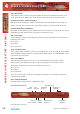
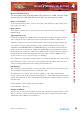
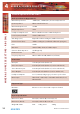
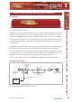
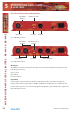
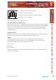
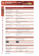
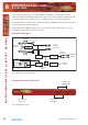
Table Of Contents
- Warranty
- Safety Information
- 1 RB-SS10 10 Way Stereo Analogue Source Selector/Mixer
- Technical Specifications RB-SS10
- 2 RB-DSS10 10 Way Stereo Digital Source Selector
- Technical Specifications RB-DSS10
- 3 RB-PMX4 10 Input, 4 Output Analogue Preset Mixer
- Technical Specifications RB-PMX4
- 4 RB-SSML1 Mic/Line Source Selector with Compressor Limiter
- Technical Specifications
- 5 RB-MA1 Single & RB-MA2 Dual Microphone Amplifiers
- Technical Specifications RB-MA1 & RB-MA2
- 6 RB-DMA2 Dual Digital Microphone Amplifier
- Technical Specifications RB-DMA2
- 7 RB-ML2 Stereo Microphone & Line Level Limiter
- Technical Specifications RB-ML2
- 8 RB-SL2 Twin Mono, or Stereo, Limiter
- Technical Specifications RB-SL2
- 9 RB-SM1 Single & RB-SM2 Dual Stereo To Mono Converter
- Technical Specifications RB-SM1 & RB-SM2
- 10 RB-LC3 3 Way Light/Power Controller
- Technical Specifications RB-LC3
- 11 RB-MM1 Mix Minus Generator
- Technical Specification RB-MM1
- Fig A: Packing List.
- Fig B: Fuse Rating Table.
- Fig C: Mains Cable Wire Colours
- Fig D: Mains Lead Table.
- Fig E: RB-RK1Small Redbox Front Rack-mount Kit .
- Fig F: RB-RK2 Small Redbox Rear Rack-mount Kit.
- Fig G: RB-RK3 Large Redbox Rear Rack-mount Kit.
- Fig 1-1: RB-SS10 Front Panel.
- Fig 1-2: RB-SS10 System Block Diagram.
- Fig 1-3: RB-SS10 Front Panel.
- Fig 1-4: RB-SS10 Rear Panel.
- Fig 1-5: Analogue Audio Inputs Pin Connections
- Fig 1-6: Remote Start Pin Connections.
- Fig 1-7: Connection Example.
- Fig 1-8: Remote Select/Switch Input Connections.
- Fig 1-9: Connection Example.
- Fig 1-10: Status Output Pin Connections.
- Fig 1-11: Connection Example.
- Fig 2-1: RB-DSS10 Front Panel.
- Fig 2-2: RB-DSS10 System Block Diagram.
- Fig 2-3: RB-DSS10 Front Panel.
- Fig 2-4: RB-DSS10 Rear Panel.
- Fig 2-5: Digital Audio Inputs and S/PDIF Output Pin Connections.
- Fig 2-6: Remote Start Pin Connections.
- Fig 2-7: Connection Example.
- Fig 2-8: Remote Select/Switch Input Connections.
- Fig 2-9: Connection Example.
- Fig 2-10: Status Output Pin Connections.
- Fig 2-11: Connection Example.
- Fig 3-1: RB-PMX4 Front Panel .
- Fig 3-2: RB-PMX4 Block Diagram.
- Fig 3-3: RB-PMX4 Rear Panel.
- Fig 3-4: RB-PMX4 Front Panel Controls.
- Fig 4-1: RB-SSML1 Front Panel.
- Fig 4-2: RB-SSML1 Block Diagram.
- Fig 4-3: RB-SSML1 Rear Panel.
- Fig 4-4: DIP Switch to Control Mic & Meter Features.
- Fig 4-5: RB-SSML1 Front Panel.
- Fig 5-1: RB-MA1 & RB-MA2 Front Panel.
- Fig 5-2: RB-MA1 & RB-MA2 Block Diagram Single Channel.
- Fig 5-3: RB-MA1 Rear Panel.
- Fig 5-4: RB-MA2 Rear Panel.
- Fig 5-5: Switch to Control LF Filter and Phantom Power.
- Fig 6-1: RB-DMA2 Front Panel.
- Fig 6-2: RB-DMA2 System Block Diagram.
- Fig 6-3: RB-DMA2 Front Panel.
- Fig 6-4: Jumpers to Disable Fine Gain Control.
- Fig 6-5: RB-DMA2 Rear Panel.
- Fig 6-6: RB-DMA2 Status Select Switches.
- Fig 6-7: RB-DMA2 Frequency and Sync Rotary Switch Selections.
- Fig 7-1: RB-ML2 Front Panel.
- Fig 7-2: RB-ML2 Block Diagram.
- Fig 7-3: RB-ML2 Rear Panel.
- Fig 7-4: Switch to Control LF Filter and Phantom Power.
- Fig 8-1: RB-SL2 Front Panel.
- Fig 8-2: RB-SL2 Block Diagram.
- Fig 8-3: RB-SL2 Rear Panel.
- Fig 9-1: RB-SM1 & RB-SM2 Front Panel.
- Fig 9-2: RB-SM1 & RB-SM2 Block Diagram Single Channel.
- Fig 9-3: RB-SM1 Rear Panel..
- Fig 9-4: RB-SM2 Rear Panel.
- Fig 10-1: RB-LC3 Front Panel.
- Fig 10-2: RB-LC3 Block Diagram.
- Fig 10-3: RB-LC3 Rear Panel
- Fig 10-4: Output 1 Configuration Setting.
- Fig 10-5: Output 2 Configuration Settings.
- Fig 10-6: Output 3 Configuration Settings.
- Fig 11-1: RB-MM1 Front Panel.
- Fig 11-2: RB-MM1 System Block Diagram.
- Fig 11-3: RB-MM1 Rear Panel.

Redbox User Handbook No 3
31
MICROPHONE AMPLIFIERS & LIMITERS - RB-MA1 & RB - M A 2
5
MICROPHONE AMPLIFIERS
& LIMITERS
5 RB-MA1 Single & RB-MA2 Dual Microphone Amplifiers
Introduction
Fig 5-1: RB-MA1 & RB-MA2 Front Panel.
The RB-MA1 consists of an independent low-noise microphone pre-amplifier for converting
microphone level signals to line level, or for driving long lines from microphones to mixing
equipment. The RB-MA2 dual microphone amplifier consists of two low noise pre amplifiers.
All connections and controls are on the rear panel. The microphone input is XLR-3 type and
is electronically balanced. The input gain can be adjusted individually by a recessed pre-set
potentiometer.
The XLR-3 line output is electronically balanced and can be wired unbalanced by grounding
the non-phase signal, allowing you to feed both balanced and unbalanced equipment.
For each channel there are independent switches to control a high pass filter (low frequency
roll-off at 125Hz) and to provide phantom power at +48V to the connected microphone. An
LED power indicator on the front panel displays the power supply connection.
The rest of this chapter will refer to both RB-MA1 and RB-MA2 unless stated otherwise.
System Block Diagram
Fig 5-2: RB-MA1 & RB-MA2 Block Diagram Single Channel.
Balanced
Microphone
Input
Phantom
power
(48V)
48V
Phantom supply on/off
Gain
L.F. Filter in/out
Professional
balanced output
Ultra low noise
high gain
amplifier
L.F.
Filter