
Manual
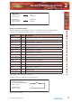
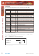

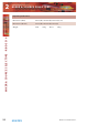

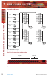
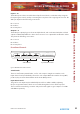
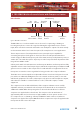
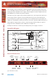
Table Of Contents
- Warranty
- Safety Information
- 1 RB-SS10 10 Way Stereo Analogue Source Selector/Mixer
- Technical Specifications RB-SS10
- 2 RB-DSS10 10 Way Stereo Digital Source Selector
- Technical Specifications RB-DSS10
- 3 RB-PMX4 10 Input, 4 Output Analogue Preset Mixer
- Technical Specifications RB-PMX4
- 4 RB-SSML1 Mic/Line Source Selector with Compressor Limiter
- Technical Specifications
- 5 RB-MA1 Single & RB-MA2 Dual Microphone Amplifiers
- Technical Specifications RB-MA1 & RB-MA2
- 6 RB-DMA2 Dual Digital Microphone Amplifier
- Technical Specifications RB-DMA2
- 7 RB-ML2 Stereo Microphone & Line Level Limiter
- Technical Specifications RB-ML2
- 8 RB-SL2 Twin Mono, or Stereo, Limiter
- Technical Specifications RB-SL2
- 9 RB-SM1 Single & RB-SM2 Dual Stereo To Mono Converter
- Technical Specifications RB-SM1 & RB-SM2
- 10 RB-LC3 3 Way Light/Power Controller
- Technical Specifications RB-LC3
- 11 RB-MM1 Mix Minus Generator
- Technical Specification RB-MM1
- Fig A: Packing List.
- Fig B: Fuse Rating Table.
- Fig C: Mains Cable Wire Colours
- Fig D: Mains Lead Table.
- Fig E: RB-RK1Small Redbox Front Rack-mount Kit .
- Fig F: RB-RK2 Small Redbox Rear Rack-mount Kit.
- Fig G: RB-RK3 Large Redbox Rear Rack-mount Kit.
- Fig 1-1: RB-SS10 Front Panel.
- Fig 1-2: RB-SS10 System Block Diagram.
- Fig 1-3: RB-SS10 Front Panel.
- Fig 1-4: RB-SS10 Rear Panel.
- Fig 1-5: Analogue Audio Inputs Pin Connections
- Fig 1-6: Remote Start Pin Connections.
- Fig 1-7: Connection Example.
- Fig 1-8: Remote Select/Switch Input Connections.
- Fig 1-9: Connection Example.
- Fig 1-10: Status Output Pin Connections.
- Fig 1-11: Connection Example.
- Fig 2-1: RB-DSS10 Front Panel.
- Fig 2-2: RB-DSS10 System Block Diagram.
- Fig 2-3: RB-DSS10 Front Panel.
- Fig 2-4: RB-DSS10 Rear Panel.
- Fig 2-5: Digital Audio Inputs and S/PDIF Output Pin Connections.
- Fig 2-6: Remote Start Pin Connections.
- Fig 2-7: Connection Example.
- Fig 2-8: Remote Select/Switch Input Connections.
- Fig 2-9: Connection Example.
- Fig 2-10: Status Output Pin Connections.
- Fig 2-11: Connection Example.
- Fig 3-1: RB-PMX4 Front Panel .
- Fig 3-2: RB-PMX4 Block Diagram.
- Fig 3-3: RB-PMX4 Rear Panel.
- Fig 3-4: RB-PMX4 Front Panel Controls.
- Fig 4-1: RB-SSML1 Front Panel.
- Fig 4-2: RB-SSML1 Block Diagram.
- Fig 4-3: RB-SSML1 Rear Panel.
- Fig 4-4: DIP Switch to Control Mic & Meter Features.
- Fig 4-5: RB-SSML1 Front Panel.
- Fig 5-1: RB-MA1 & RB-MA2 Front Panel.
- Fig 5-2: RB-MA1 & RB-MA2 Block Diagram Single Channel.
- Fig 5-3: RB-MA1 Rear Panel.
- Fig 5-4: RB-MA2 Rear Panel.
- Fig 5-5: Switch to Control LF Filter and Phantom Power.
- Fig 6-1: RB-DMA2 Front Panel.
- Fig 6-2: RB-DMA2 System Block Diagram.
- Fig 6-3: RB-DMA2 Front Panel.
- Fig 6-4: Jumpers to Disable Fine Gain Control.
- Fig 6-5: RB-DMA2 Rear Panel.
- Fig 6-6: RB-DMA2 Status Select Switches.
- Fig 6-7: RB-DMA2 Frequency and Sync Rotary Switch Selections.
- Fig 7-1: RB-ML2 Front Panel.
- Fig 7-2: RB-ML2 Block Diagram.
- Fig 7-3: RB-ML2 Rear Panel.
- Fig 7-4: Switch to Control LF Filter and Phantom Power.
- Fig 8-1: RB-SL2 Front Panel.
- Fig 8-2: RB-SL2 Block Diagram.
- Fig 8-3: RB-SL2 Rear Panel.
- Fig 9-1: RB-SM1 & RB-SM2 Front Panel.
- Fig 9-2: RB-SM1 & RB-SM2 Block Diagram Single Channel.
- Fig 9-3: RB-SM1 Rear Panel..
- Fig 9-4: RB-SM2 Rear Panel.
- Fig 10-1: RB-LC3 Front Panel.
- Fig 10-2: RB-LC3 Block Diagram.
- Fig 10-3: RB-LC3 Rear Panel
- Fig 10-4: Output 1 Configuration Setting.
- Fig 10-5: Output 2 Configuration Settings.
- Fig 10-6: Output 3 Configuration Settings.
- Fig 11-1: RB-MM1 Front Panel.
- Fig 11-2: RB-MM1 System Block Diagram.
- Fig 11-3: RB-MM1 Rear Panel.

26
Redbox User Handbook No 3
MIXER & SOURCE SELECTORS
The metering is carried out after the compressor/limiter section and consists of two rows
of 12 round LEDs showing levels between -17dB and +11dB. An internal jumper allows the
metering to follow either the stereo output, or the headphone monitor outputs and a rear
panel DIPswitch can disable the peak hold display.
The XLR-3 stereo line output can be fed from either the mic or line input, but not the stereo
monitor input. The line output is electronically balanced and can be wired unbalanced
by grounding the non-phase signal, allowing you to feed both balanced and unbalanced
equipment. A pushbutton switch is provided to reduce the output by 10dB for this purpose.
The headphone output volume control is on the front panel. Each headphone output is
designed to drive 150 mW into 32Ω to 600Ω stereo headphones.
An LED power indicator on the front panel displays the power supply connection.
System Block Diagram
Fig 4-2: RB-SSML1 Block Diagram.
Rear Panel Connections
Fig 4-3: RB-SSML1 Rear Panel.
M
M
Phantom
Po
wer (48V)
Phantom
On/Off
L.F. Filter
In/Out
L.F. Filter
Mic.
Vo
lume
Gain
Fixe
d
Gain
Analogue
Switch
Compression
Threshol
d
Mi
c
Fixe
d Gain
Fixe
d Gain
Fixed Gain
Fixe
d Gain
Stereo
Monito
r
Stereo
Line
L
Line Volume L
Line Volume R
Line Volume L
Line Volume R
R
L
R
Fixed
Gain
Co
mpressor
Controls
Jumper
Jumper
Au
dio Output
Amplifier
Vo
lume
Stereo Jack
Output
Stereo Jack
Output
LED Level
Meter Driv
ers
Peak
Hold
On/Off
Stereo
Output
Stereo
Monitor
Inputs
Stereo Line
Inputs
Stereo
Outputs
Monitor
Gain Pad
Option
Switches
Stereo Line
Gain Pad
Stereo Output
Gain Pad
Monitor
Volume
Mic
Input
Mic
Gain
MIXER & SOURCE SELECTORS - RB -SSML1
4