
Handbook


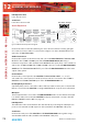


Table Of Contents
- Fig A: Packing List.
- Fig B: Mains Cable Wire Colours
- Fig C: Mains Lead Table.
- Fig D: RB-RK1Small Redbox Front Rack-mount Kit .
- Fig E: RB-RK2 Small Redbox Rear Rack-mount Kit.
- Fig F: RB-RK3 Large Redbox Rear Rack-mount Kit.
- Fig 1-1: RB-SS10 Front Panel.
- Fig 1-2: RB-SS10 System Block Diagram.
- Fig 1-3: RB-SS10 Front Panel.
- Fig 1-4: RB-SS10 Rear Panel.
- Fig 1-5: Analogue Audio Inputs Pin Connections
- Fig 1-6: Remote Start Pin Connections.
- Fig 1-7: Connection Example.
- Fig 1-8: Remote Select/Switch Input Connections.
- Fig 1-9: Connection Example.
- Fig 1-10: Status Output Pin Connections.
- Fig 1-11: Connection Example.
- Fig 2-1: RB-DSS10 Front Panel.
- Fig 2-2: RB-DSS10 System Block Diagram.
- Fig 2-3: RB-DSS10 Front Panel.
- Fig 2-4: RB-DSS10 Rear Panel.
- Fig 2-5: Digital Audio Inputs and S/PDIF Output Pin Connections.
- Fig 2-6: Remote Start Pin Connections.
- Fig 2-7: Connection Example.
- Fig 2-8: Remote Select/Switch Input Connections.
- Fig 2-9: Connection Example.
- Fig 2-10: Status Output Pin Connections.
- Fig 2-11: Connection Example.
- Fig 3-1: RB-PMX4 Front Panel .
- Fig 3-2: RB-PMX4 Block Diagram.
- Fig 3-3: RB-PMX4 Rear Panel.
- Fig 3-4: RB-PMX4 Front Panel Controls.
- Fig 4-1: RB-SSML1 Front Panel.
- Fig 4-2: RB-SSML1 Block Diagram.
- Fig 4-3: RB-SSML1 Rear Panel.
- Fig 4-4: DIP Switch to Control Mic & Meter Features.
- Fig 4-5: RB-SSML1 Front Panel.
- Fig 5-1: RB-MA1 & RB-MA2 Front Panel.
- Fig 5-2: RB-MA1 & RB-MA2 Block Diagram Single Channel.
- Fig 5-3: RB-MA1 Rear Panel.
- Fig 5-4: RB-MA2 Rear Panel.
- Fig 5-5: Switch to Control LF Filter and Phantom Power.
- Fig 6-1: RB-DMA2 Front Panel.
- Fig 6-2: RB-DMA2 System Block Diagram.
- Fig 6-3: RB-DMA2 Front Panel.
- Fig 6-4: Jumpers to Disable Fine Gain Control.
- Fig 6-5: RB-DMA2 Rear Panel.
- Fig 6-6: RB-DMA2 Status Select Switches.
- Fig 6-7: RB-DMA2 Frequency and Sync Rotary Switch Selections.
- Fig 7-1: RB-ML2 Front Panel.
- Fig 7-2: RB-ML2 Block Diagram.
- Fig 7-3: RB-ML2 Rear Panel.
- Fig 7-4: Switch to Control LF Filter and Phantom Power.
- Fig 8-1: RB-SL2 Front Panel.
- Fig 8-2: RB-SL2 Block Diagram.
- Fig 8-3: RB-SL2 Rear Panel.
- Fig 9-1: RB-SM1 & RB-SM2 Front Panel.
- Fig 9-2: RB-SM1 & RB-SM2 Block Diagram Single Channel.
- Fig 9-3: RB-SM1 Rear Panel..
- Fig 9-4: RB-SM2 Rear Panel.
- Fig 10-1: RB-LC3 Front Panel.
- Fig 10-2: RB-LC3 Block Diagram.
- Fig 10-3: RB-LC3 Rear Panel
- Fig 10-4: Output 1 Configuration Setting.
- Fig 10-5: Output 2 Configuration Settings.
- Fig 10-6: Output 3 Configuration Settings.
- Fig 11-1: RB-MM1 Front Panel.
- Fig 11-2: RB-MM1 System Block Diagram.
- Fig 11-3: RB-MM1 Rear Panel.
- Fig 12-1: RB-OA3 Front Panel.
- Fig 12-2: RB-OA3 System Block Diagram.
- Fig 12-3: RB-OA3 Rear Panel.
- Fig 12-4: RB-OA3 Unit Identity Definitions.
- Fig 12-5: RB-OA3 Unit Identity Reset Settings.
- Fig 12-6: RB-OA3 Studio Expansion Diagram.
- Fig 12-7: RB-OA3 Bus Expansion Diagram.
- Fig 12-8: RB-OA3 Studio & Bus Expansion Diagram.
- Fig 12-9: RB-OA3 Multiple RB-OA3 Expansion Diagram.
- Fig 12-10: Offer & Accept Button Operation (Flashing is indicated by radial lines around a button).
- Fig 12-11: RB-OA3 LSO Expansion Connector Definitions.
- Fig 12-12: RB-OA3 LSO Expansion Connector Details.
- Fig 12-13: RB-OA3 Mix Input Connector Definitions.
- Fig 12-14: RB-OA3 Mix Input Connector Details.
- Fig 12-15: RB-OA3 Transmission I/O Connector Definitions.
- Fig 12-16: RB-OA3 Transmission Outputs Connector Details.
- Fig 12-17: RB-OA3 Studio 1-3 Audio Connector Definitions.
- Fig 12-18: RB-OA3 Studio 1-3 Audio Connector Details.
- Fig 12-19: RB-OA3 Studio 1-3 Control Connector Definitions.
- Fig 12-20: RB-OA3 Switch & Lamp Control Details.
- Fig 12-21: RB-OA3 Profanity Delay Control Connector Definitions..
- Fig 12-22: RB-OA3 Profanity Delay Control Connector Details.
- Fig 12-23: RB-OA3R Front Panel.
- Fig 12-26: RB-OA3R Pin Out Definitions.
- Fig 12-27: RB-OA3R Pin Out Positions.
- Fig 13-1: XLR Connectors.
- Fig 13-2: RCA Phono Connector.
- Fig 13-3: ¼” Jack Connector.
- Fig 13-4: 25 Way D-Type Connectors.
- Fig 13-5: 15 Way D-Type Connectors.
- Fig 13-6: 9 Way D-Type Connectors.
- Warranty
- Safety Information
- 1 RB-SS10 10 Way Stereo Analogue Source Selector/Mixer
- Technical Specifications RB-SS10
- 2 RB-DSS10 10 Way Stereo Digital Source Selector
- Technical Specifications RB-DSS10
- 3 RB-PMX4 10 Input, 4 Output Analogue Preset Mixer
- Technical Specifications RB-PMX4
- 4 RB-SSML1 Mic/Line Source Selector with Compressor Limiter
- Technical Specifications RB-SSML1
- 5 RB-MA1 Single & RB-MA2 Dual Microphone Amplifiers
- Technical Specifications RB-MA1 & RB-MA2
- 6 RB-DMA2 Dual Digital Microphone Amplifier
- Technical Specifications RB-DMA2
- 7 RB-ML2 Stereo Microphone & Line Level Limiter
- Technical Specifications RB-ML2
- 8 RB-SL2 Twin Mono, or Stereo, Limiter
- Technical Specifications RB-SL2
- 9 RB-SM1 Single & RB-SM2 Dual Stereo To Mono Converter
- Technical Specifications RB-SM1 & RB-SM2
- 10 RB-LC3 3 Way Light/Power Controller
- Technical Specifications RB-LC3
- 11 RB-MM1 Mix Minus Generator
- Technical Specification RB-MM1
- 12 RB-OA3 3 Studio On-Air Switcher
- Introduction
- System Block Diagram
- Rear Panel Connections and Operation
- Installation Guide for the RB-OA3
- Configuring for OperationThe RB-OA3 can be used in both single (MASTER) and multiple expansion modes.
- Single (MASTER) Mode When used as a single (MASTER) unit, the RB-OA3 is used to switch 3 stereo busses between 3 studios, allowing them to share the same transmission path and peripheral devices such as hybrids or profanity delays. A single unit must always be configured as a MASTER unit.
- Serial PortsConnect the serial ports of the MASTER and BUS EXPANSION SLAVE units together using a standard RJ45 network cable (not a cross-over cable).Studio & Bus (4 Unit) Expansion
- Indications – How The LEDS Are Used
- Operational Modes
- Rear Panel Connections & Operation
- Technical Specification RB-OA3
- RB-OA3R Remote Switch Panel For RB-OA3
- Technical Specification RB-OA3R
- RB-OA3C Expansion Unit Cable Kit For RB-OA3
- Technical Specification RB-OA3C
- 13 Connectors & Cabling
- 14 Glossary

76
Redbox User Handbook No 3
GENERAL INTERFACES
GENERAL INTERFACES - RB-OA3
12
in. When the unit is operating as a STUDIO EXPANSION SLAVE, if one of the MASTER unit’s
studios is routed to the transmission path, STUDIO 1 LED will always be illuminated. If one of
SLAVE’S studios is selected, the MASTER unit’s studio indications will all be extinguished.
CONTROL PANEL LEDS
Each of the control panel connectors has the ability to switch on four LEDS. In the case of
the S2-MTBS and the RB-OA3R, the LEDS are built into the buttons.
OFFER
This LED is used to show whether the system is currently in OFFER mode. This LED is
illuminated while the unit is on oer and extinguished otherwise. If this LED ashes this
means that the unit is currently in SUSTAIN ACTIVE mode.
ACCEPT
This LED is illuminated if the studio is currently on the transmission path. In SUSTAIN ARMED
mode this LED will ash repeatedly until the specic studio is selected. The ACCEPT LED will
always ash to indicate SUSTAIN ARMED mode.
DELAY
This LED is used to show whether the studio has activated a delay pulse. It is illuminated
when a delay pulse is activated.
DUMP
This LED is used to show whether the studio has activated a dump pulse. It is illuminated
when a dump pulse is activated.
EMERGENCY MODE
If the MASTER loses contact with any of the SLAVES, the SLAVES will enter emergency
mode. In emergency mode all the LEDS except the power led will ash repeatedly until
contact with the master is re-established.
Operational Modes
OFFER
If a studio is transmitting, this mode is used to oer the transmission path to other studios.
When the OFFER button is pressed, the OFFER button in all studios is illuminated. This
unlocks the operation of the ACCEPT button in all other studios. To remove this mode,
simply press the OFFER button again. Pressing this also switches the current studio to the
LSO bus.
ACCEPT
This mode is used to accept the transmission path. To do this, press the ACCEPT button once
the oer has been made. Once the studio has accepted, this switches the OFFER, DELAY,
DUMP and SUSTAIN functions to that studio.
SUSTAIN
This mode is used to switch to a sustaining service, for example, a PC automation system,
which conventionally wouldn’t be in its own studio and would therefore need external