
Handbook

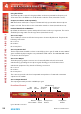


Table Of Contents
- Fig A: Packing List.
- Fig B: Mains Cable Wire Colours
- Fig C: Mains Lead Table.
- Fig D: RB-RK1Small Redbox Front Rack-mount Kit .
- Fig E: RB-RK2 Small Redbox Rear Rack-mount Kit.
- Fig F: RB-RK3 Large Redbox Rear Rack-mount Kit.
- Fig 1-1: RB-SS10 Front Panel.
- Fig 1-2: RB-SS10 System Block Diagram.
- Fig 1-3: RB-SS10 Front Panel.
- Fig 1-4: RB-SS10 Rear Panel.
- Fig 1-5: Analogue Audio Inputs Pin Connections
- Fig 1-6: Remote Start Pin Connections.
- Fig 1-7: Connection Example.
- Fig 1-8: Remote Select/Switch Input Connections.
- Fig 1-9: Connection Example.
- Fig 1-10: Status Output Pin Connections.
- Fig 1-11: Connection Example.
- Fig 2-1: RB-DSS10 Front Panel.
- Fig 2-2: RB-DSS10 System Block Diagram.
- Fig 2-3: RB-DSS10 Front Panel.
- Fig 2-4: RB-DSS10 Rear Panel.
- Fig 2-5: Digital Audio Inputs and S/PDIF Output Pin Connections.
- Fig 2-6: Remote Start Pin Connections.
- Fig 2-7: Connection Example.
- Fig 2-8: Remote Select/Switch Input Connections.
- Fig 2-9: Connection Example.
- Fig 2-10: Status Output Pin Connections.
- Fig 2-11: Connection Example.
- Fig 3-1: RB-PMX4 Front Panel .
- Fig 3-2: RB-PMX4 Block Diagram.
- Fig 3-3: RB-PMX4 Rear Panel.
- Fig 3-4: RB-PMX4 Front Panel Controls.
- Fig 4-1: RB-SSML1 Front Panel.
- Fig 4-2: RB-SSML1 Block Diagram.
- Fig 4-3: RB-SSML1 Rear Panel.
- Fig 4-4: DIP Switch to Control Mic & Meter Features.
- Fig 4-5: RB-SSML1 Front Panel.
- Fig 5-1: RB-MA1 & RB-MA2 Front Panel.
- Fig 5-2: RB-MA1 & RB-MA2 Block Diagram Single Channel.
- Fig 5-3: RB-MA1 Rear Panel.
- Fig 5-4: RB-MA2 Rear Panel.
- Fig 5-5: Switch to Control LF Filter and Phantom Power.
- Fig 6-1: RB-DMA2 Front Panel.
- Fig 6-2: RB-DMA2 System Block Diagram.
- Fig 6-3: RB-DMA2 Front Panel.
- Fig 6-4: Jumpers to Disable Fine Gain Control.
- Fig 6-5: RB-DMA2 Rear Panel.
- Fig 6-6: RB-DMA2 Status Select Switches.
- Fig 6-7: RB-DMA2 Frequency and Sync Rotary Switch Selections.
- Fig 7-1: RB-ML2 Front Panel.
- Fig 7-2: RB-ML2 Block Diagram.
- Fig 7-3: RB-ML2 Rear Panel.
- Fig 7-4: Switch to Control LF Filter and Phantom Power.
- Fig 8-1: RB-SL2 Front Panel.
- Fig 8-2: RB-SL2 Block Diagram.
- Fig 8-3: RB-SL2 Rear Panel.
- Fig 9-1: RB-SM1 & RB-SM2 Front Panel.
- Fig 9-2: RB-SM1 & RB-SM2 Block Diagram Single Channel.
- Fig 9-3: RB-SM1 Rear Panel..
- Fig 9-4: RB-SM2 Rear Panel.
- Fig 10-1: RB-LC3 Front Panel.
- Fig 10-2: RB-LC3 Block Diagram.
- Fig 10-3: RB-LC3 Rear Panel
- Fig 10-4: Output 1 Configuration Setting.
- Fig 10-5: Output 2 Configuration Settings.
- Fig 10-6: Output 3 Configuration Settings.
- Fig 11-1: RB-MM1 Front Panel.
- Fig 11-2: RB-MM1 System Block Diagram.
- Fig 11-3: RB-MM1 Rear Panel.
- Fig 12-1: RB-OA3 Front Panel.
- Fig 12-2: RB-OA3 System Block Diagram.
- Fig 12-3: RB-OA3 Rear Panel.
- Fig 12-4: RB-OA3 Unit Identity Definitions.
- Fig 12-5: RB-OA3 Unit Identity Reset Settings.
- Fig 12-6: RB-OA3 Studio Expansion Diagram.
- Fig 12-7: RB-OA3 Bus Expansion Diagram.
- Fig 12-8: RB-OA3 Studio & Bus Expansion Diagram.
- Fig 12-9: RB-OA3 Multiple RB-OA3 Expansion Diagram.
- Fig 12-10: Offer & Accept Button Operation (Flashing is indicated by radial lines around a button).
- Fig 12-11: RB-OA3 LSO Expansion Connector Definitions.
- Fig 12-12: RB-OA3 LSO Expansion Connector Details.
- Fig 12-13: RB-OA3 Mix Input Connector Definitions.
- Fig 12-14: RB-OA3 Mix Input Connector Details.
- Fig 12-15: RB-OA3 Transmission I/O Connector Definitions.
- Fig 12-16: RB-OA3 Transmission Outputs Connector Details.
- Fig 12-17: RB-OA3 Studio 1-3 Audio Connector Definitions.
- Fig 12-18: RB-OA3 Studio 1-3 Audio Connector Details.
- Fig 12-19: RB-OA3 Studio 1-3 Control Connector Definitions.
- Fig 12-20: RB-OA3 Switch & Lamp Control Details.
- Fig 12-21: RB-OA3 Profanity Delay Control Connector Definitions..
- Fig 12-22: RB-OA3 Profanity Delay Control Connector Details.
- Fig 12-23: RB-OA3R Front Panel.
- Fig 12-26: RB-OA3R Pin Out Definitions.
- Fig 12-27: RB-OA3R Pin Out Positions.
- Fig 13-1: XLR Connectors.
- Fig 13-2: RCA Phono Connector.
- Fig 13-3: ¼” Jack Connector.
- Fig 13-4: 25 Way D-Type Connectors.
- Fig 13-5: 15 Way D-Type Connectors.
- Fig 13-6: 9 Way D-Type Connectors.
- Warranty
- Safety Information
- 1 RB-SS10 10 Way Stereo Analogue Source Selector/Mixer
- Technical Specifications RB-SS10
- 2 RB-DSS10 10 Way Stereo Digital Source Selector
- Technical Specifications RB-DSS10
- 3 RB-PMX4 10 Input, 4 Output Analogue Preset Mixer
- Technical Specifications RB-PMX4
- 4 RB-SSML1 Mic/Line Source Selector with Compressor Limiter
- Technical Specifications RB-SSML1
- 5 RB-MA1 Single & RB-MA2 Dual Microphone Amplifiers
- Technical Specifications RB-MA1 & RB-MA2
- 6 RB-DMA2 Dual Digital Microphone Amplifier
- Technical Specifications RB-DMA2
- 7 RB-ML2 Stereo Microphone & Line Level Limiter
- Technical Specifications RB-ML2
- 8 RB-SL2 Twin Mono, or Stereo, Limiter
- Technical Specifications RB-SL2
- 9 RB-SM1 Single & RB-SM2 Dual Stereo To Mono Converter
- Technical Specifications RB-SM1 & RB-SM2
- 10 RB-LC3 3 Way Light/Power Controller
- Technical Specifications RB-LC3
- 11 RB-MM1 Mix Minus Generator
- Technical Specification RB-MM1
- 12 RB-OA3 3 Studio On-Air Switcher
- Introduction
- System Block Diagram
- Rear Panel Connections and Operation
- Installation Guide for the RB-OA3
- Configuring for OperationThe RB-OA3 can be used in both single (MASTER) and multiple expansion modes.
- Single (MASTER) Mode When used as a single (MASTER) unit, the RB-OA3 is used to switch 3 stereo busses between 3 studios, allowing them to share the same transmission path and peripheral devices such as hybrids or profanity delays. A single unit must always be configured as a MASTER unit.
- Serial PortsConnect the serial ports of the MASTER and BUS EXPANSION SLAVE units together using a standard RJ45 network cable (not a cross-over cable).Studio & Bus (4 Unit) Expansion
- Indications – How The LEDS Are Used
- Operational Modes
- Rear Panel Connections & Operation
- Technical Specification RB-OA3
- RB-OA3R Remote Switch Panel For RB-OA3
- Technical Specification RB-OA3R
- RB-OA3C Expansion Unit Cable Kit For RB-OA3
- Technical Specification RB-OA3C
- 13 Connectors & Cabling
- 14 Glossary

Redbox User Handbook No 3
33
Fig 5-5: Switch to Control LF Filter and Phantom Power.
Using Phantom Powered Microphones
For the input channel there are independent switches to provide phantom power at +48V
to the connected microphones. With phantom power selected, a voltage of +48V is applied
to pins 2 and 3 of the XLR connector to power the microphone, supplied through 6k8
resistors giving a current of 14mA. Phantom power is used when the switch is pointing
towards the arrow.
Using the LF Filter
A switch also provides control for a high pass lter with low frequency roll o at 125Hz. The
lter is in when the switch is in the down position (towards the arrow).
Output
The XLR 3 pin plug output connector is electronically balanced and can be wired
unbalanced by grounding the non-phase signal, allowing you to feed balanced and
unbalanced equipment. It has the following connections:
Pin 1: Screen
Pin 2: Phase
Pin 3: Non-phase
The connector provides a line level output with an impedance of <50Ω and a maximum
output level of +28dBu.
MICROP HONE AMPLIF IERS
& LIMITERS
On On
On On
2 3 4
1
1 Channel 1 Low Frequency (LF) Filter
2 Channel 1 Phantom Power
3 Channel 2 Phantom Power (only applies to MA2)
4 Channel 2 Low Frequency
MICROPHONE AMPLIFIERS & LIMITERS - RB-MA1 & RB-MA2
5