
Handbook
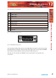


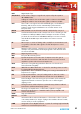


Table Of Contents
- Fig A: Packing List.
- Fig B: Mains Cable Wire Colours
- Fig C: Mains Lead Table.
- Fig D: RB-RK1Small Redbox Front Rack-mount Kit .
- Fig E: RB-RK2 Small Redbox Rear Rack-mount Kit.
- Fig F: RB-RK3 Large Redbox Rear Rack-mount Kit.
- Fig 1-1: RB-SS10 Front Panel.
- Fig 1-2: RB-SS10 System Block Diagram.
- Fig 1-3: RB-SS10 Front Panel.
- Fig 1-4: RB-SS10 Rear Panel.
- Fig 1-5: Analogue Audio Inputs Pin Connections
- Fig 1-6: Remote Start Pin Connections.
- Fig 1-7: Connection Example.
- Fig 1-8: Remote Select/Switch Input Connections.
- Fig 1-9: Connection Example.
- Fig 1-10: Status Output Pin Connections.
- Fig 1-11: Connection Example.
- Fig 2-1: RB-DSS10 Front Panel.
- Fig 2-2: RB-DSS10 System Block Diagram.
- Fig 2-3: RB-DSS10 Front Panel.
- Fig 2-4: RB-DSS10 Rear Panel.
- Fig 2-5: Digital Audio Inputs and S/PDIF Output Pin Connections.
- Fig 2-6: Remote Start Pin Connections.
- Fig 2-7: Connection Example.
- Fig 2-8: Remote Select/Switch Input Connections.
- Fig 2-9: Connection Example.
- Fig 2-10: Status Output Pin Connections.
- Fig 2-11: Connection Example.
- Fig 3-1: RB-PMX4 Front Panel .
- Fig 3-2: RB-PMX4 Block Diagram.
- Fig 3-3: RB-PMX4 Rear Panel.
- Fig 3-4: RB-PMX4 Front Panel Controls.
- Fig 4-1: RB-SSML1 Front Panel.
- Fig 4-2: RB-SSML1 Block Diagram.
- Fig 4-3: RB-SSML1 Rear Panel.
- Fig 4-4: DIP Switch to Control Mic & Meter Features.
- Fig 4-5: RB-SSML1 Front Panel.
- Fig 5-1: RB-MA1 & RB-MA2 Front Panel.
- Fig 5-2: RB-MA1 & RB-MA2 Block Diagram Single Channel.
- Fig 5-3: RB-MA1 Rear Panel.
- Fig 5-4: RB-MA2 Rear Panel.
- Fig 5-5: Switch to Control LF Filter and Phantom Power.
- Fig 6-1: RB-DMA2 Front Panel.
- Fig 6-2: RB-DMA2 System Block Diagram.
- Fig 6-3: RB-DMA2 Front Panel.
- Fig 6-4: Jumpers to Disable Fine Gain Control.
- Fig 6-5: RB-DMA2 Rear Panel.
- Fig 6-6: RB-DMA2 Status Select Switches.
- Fig 6-7: RB-DMA2 Frequency and Sync Rotary Switch Selections.
- Fig 7-1: RB-ML2 Front Panel.
- Fig 7-2: RB-ML2 Block Diagram.
- Fig 7-3: RB-ML2 Rear Panel.
- Fig 7-4: Switch to Control LF Filter and Phantom Power.
- Fig 8-1: RB-SL2 Front Panel.
- Fig 8-2: RB-SL2 Block Diagram.
- Fig 8-3: RB-SL2 Rear Panel.
- Fig 9-1: RB-SM1 & RB-SM2 Front Panel.
- Fig 9-2: RB-SM1 & RB-SM2 Block Diagram Single Channel.
- Fig 9-3: RB-SM1 Rear Panel..
- Fig 9-4: RB-SM2 Rear Panel.
- Fig 10-1: RB-LC3 Front Panel.
- Fig 10-2: RB-LC3 Block Diagram.
- Fig 10-3: RB-LC3 Rear Panel
- Fig 10-4: Output 1 Configuration Setting.
- Fig 10-5: Output 2 Configuration Settings.
- Fig 10-6: Output 3 Configuration Settings.
- Fig 11-1: RB-MM1 Front Panel.
- Fig 11-2: RB-MM1 System Block Diagram.
- Fig 11-3: RB-MM1 Rear Panel.
- Fig 12-1: RB-OA3 Front Panel.
- Fig 12-2: RB-OA3 System Block Diagram.
- Fig 12-3: RB-OA3 Rear Panel.
- Fig 12-4: RB-OA3 Unit Identity Definitions.
- Fig 12-5: RB-OA3 Unit Identity Reset Settings.
- Fig 12-6: RB-OA3 Studio Expansion Diagram.
- Fig 12-7: RB-OA3 Bus Expansion Diagram.
- Fig 12-8: RB-OA3 Studio & Bus Expansion Diagram.
- Fig 12-9: RB-OA3 Multiple RB-OA3 Expansion Diagram.
- Fig 12-10: Offer & Accept Button Operation (Flashing is indicated by radial lines around a button).
- Fig 12-11: RB-OA3 LSO Expansion Connector Definitions.
- Fig 12-12: RB-OA3 LSO Expansion Connector Details.
- Fig 12-13: RB-OA3 Mix Input Connector Definitions.
- Fig 12-14: RB-OA3 Mix Input Connector Details.
- Fig 12-15: RB-OA3 Transmission I/O Connector Definitions.
- Fig 12-16: RB-OA3 Transmission Outputs Connector Details.
- Fig 12-17: RB-OA3 Studio 1-3 Audio Connector Definitions.
- Fig 12-18: RB-OA3 Studio 1-3 Audio Connector Details.
- Fig 12-19: RB-OA3 Studio 1-3 Control Connector Definitions.
- Fig 12-20: RB-OA3 Switch & Lamp Control Details.
- Fig 12-21: RB-OA3 Profanity Delay Control Connector Definitions..
- Fig 12-22: RB-OA3 Profanity Delay Control Connector Details.
- Fig 12-23: RB-OA3R Front Panel.
- Fig 12-26: RB-OA3R Pin Out Definitions.
- Fig 12-27: RB-OA3R Pin Out Positions.
- Fig 13-1: XLR Connectors.
- Fig 13-2: RCA Phono Connector.
- Fig 13-3: ¼” Jack Connector.
- Fig 13-4: 25 Way D-Type Connectors.
- Fig 13-5: 15 Way D-Type Connectors.
- Fig 13-6: 9 Way D-Type Connectors.
- Warranty
- Safety Information
- 1 RB-SS10 10 Way Stereo Analogue Source Selector/Mixer
- Technical Specifications RB-SS10
- 2 RB-DSS10 10 Way Stereo Digital Source Selector
- Technical Specifications RB-DSS10
- 3 RB-PMX4 10 Input, 4 Output Analogue Preset Mixer
- Technical Specifications RB-PMX4
- 4 RB-SSML1 Mic/Line Source Selector with Compressor Limiter
- Technical Specifications RB-SSML1
- 5 RB-MA1 Single & RB-MA2 Dual Microphone Amplifiers
- Technical Specifications RB-MA1 & RB-MA2
- 6 RB-DMA2 Dual Digital Microphone Amplifier
- Technical Specifications RB-DMA2
- 7 RB-ML2 Stereo Microphone & Line Level Limiter
- Technical Specifications RB-ML2
- 8 RB-SL2 Twin Mono, or Stereo, Limiter
- Technical Specifications RB-SL2
- 9 RB-SM1 Single & RB-SM2 Dual Stereo To Mono Converter
- Technical Specifications RB-SM1 & RB-SM2
- 10 RB-LC3 3 Way Light/Power Controller
- Technical Specifications RB-LC3
- 11 RB-MM1 Mix Minus Generator
- Technical Specification RB-MM1
- 12 RB-OA3 3 Studio On-Air Switcher
- Introduction
- System Block Diagram
- Rear Panel Connections and Operation
- Installation Guide for the RB-OA3
- Configuring for OperationThe RB-OA3 can be used in both single (MASTER) and multiple expansion modes.
- Single (MASTER) Mode When used as a single (MASTER) unit, the RB-OA3 is used to switch 3 stereo busses between 3 studios, allowing them to share the same transmission path and peripheral devices such as hybrids or profanity delays. A single unit must always be configured as a MASTER unit.
- Serial PortsConnect the serial ports of the MASTER and BUS EXPANSION SLAVE units together using a standard RJ45 network cable (not a cross-over cable).Studio & Bus (4 Unit) Expansion
- Indications – How The LEDS Are Used
- Operational Modes
- Rear Panel Connections & Operation
- Technical Specification RB-OA3
- RB-OA3R Remote Switch Panel For RB-OA3
- Technical Specification RB-OA3R
- RB-OA3C Expansion Unit Cable Kit For RB-OA3
- Technical Specification RB-OA3C
- 13 Connectors & Cabling
- 14 Glossary

Redbox User Handbook No 3
93
14
GLOSSARY
GLOSSARY
DAT Digital Audio Tape.
dB (decibel) A ratio of two voltages or signal levels, expressed by the equation
dB=20LOG(V1/V2)
Adding the sux “u” denotes that the signal is relative to 0.775V RMS.
Adding the sux “v” denotes that the signal is relative to 1V RMS.
DCF This is radio code signal sourced from Mainingen, near Frankfurt in
Germany, which can be used to automatically synchronize the
Sentinel+ audio logger and PC time to an accurate atomic clock,
European Time.
DDS & DDS and DDS-2 are world-wide standards established by Sony and
DDS-2 Hewlett-Packard which introduce many levels of error checking as data
is written to a DAT tape. DDS(-2) drives and tapes are used in security
products all over the world. 120m DDS-2 DAT tapes are more accurate
and reliable than DDS tapes and are able to store twice as much
audio data.
DI Direct Inject - a means of driving audio, usually from an instrument such
as a guitar, to allow the audio signal to be fed directly into a sound
desk input.
DLS Dynamic Label segment - a text message scheme used in digital radio,
usually to carry information about the programme. Like the radio-text
scheme used in RDS.
DSP Digital Signal Processing.
EBU European Broadcasting Union.
EIN Equivalent input noise. It is the ratio of output noise to the gain. It
describes the level of noise which would need to be fed into an ideal
amplier to produce the measured output noise.
ENG (Electronic news gathering). Machines that can record audio and
video information digitally.
EON (RDS) Enhance Other Networks - a scheme for switching a listener’s radio
to another Eective Radiated Power.
EQ (Equalisation). This is a method of cutting or boosting selected bands of
frequencies in a signal.
FM Frequency Modulation - a way of sending audio or data over a radio
carrier, the 88 - 108 Broadcast Band is often known as the FM Band.
FSD Full Scale Digits - This is the analogue representation of the maximum
digital value that the converter in question can see before digital
clipping occurs.
3G Third generation mobile telephone system that may allow broadband
transmission of Global Positioning System.
Gain The degree of amplication, or attenuation, applied to a signal.
GRAM Gramophone Reproducer - a turntable with a ‘pick-up’ amplier and
remote start interface.
HDLC High Speed Data Link.
Hybrid See TBU
IEC International Elecrotechnical Commision - often used to refer to a mains
connectivity standard, i.e. A type of plug/socket similar to that of a kettle,
used on most pro-audio equipment.
ISDN Integrated Services Digital Network - a system for sending high bandwidth
material over standard telephone lines.