
Handbook
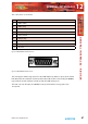


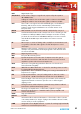


Table Of Contents
- Fig A: Packing List.
- Fig B: Mains Cable Wire Colours
- Fig C: Mains Lead Table.
- Fig D: RB-RK1Small Redbox Front Rack-mount Kit .
- Fig E: RB-RK2 Small Redbox Rear Rack-mount Kit.
- Fig F: RB-RK3 Large Redbox Rear Rack-mount Kit.
- Fig 1-1: RB-SS10 Front Panel.
- Fig 1-2: RB-SS10 System Block Diagram.
- Fig 1-3: RB-SS10 Front Panel.
- Fig 1-4: RB-SS10 Rear Panel.
- Fig 1-5: Analogue Audio Inputs Pin Connections
- Fig 1-6: Remote Start Pin Connections.
- Fig 1-7: Connection Example.
- Fig 1-8: Remote Select/Switch Input Connections.
- Fig 1-9: Connection Example.
- Fig 1-10: Status Output Pin Connections.
- Fig 1-11: Connection Example.
- Fig 2-1: RB-DSS10 Front Panel.
- Fig 2-2: RB-DSS10 System Block Diagram.
- Fig 2-3: RB-DSS10 Front Panel.
- Fig 2-4: RB-DSS10 Rear Panel.
- Fig 2-5: Digital Audio Inputs and S/PDIF Output Pin Connections.
- Fig 2-6: Remote Start Pin Connections.
- Fig 2-7: Connection Example.
- Fig 2-8: Remote Select/Switch Input Connections.
- Fig 2-9: Connection Example.
- Fig 2-10: Status Output Pin Connections.
- Fig 2-11: Connection Example.
- Fig 3-1: RB-PMX4 Front Panel .
- Fig 3-2: RB-PMX4 Block Diagram.
- Fig 3-3: RB-PMX4 Rear Panel.
- Fig 3-4: RB-PMX4 Front Panel Controls.
- Fig 4-1: RB-SSML1 Front Panel.
- Fig 4-2: RB-SSML1 Block Diagram.
- Fig 4-3: RB-SSML1 Rear Panel.
- Fig 4-4: DIP Switch to Control Mic & Meter Features.
- Fig 4-5: RB-SSML1 Front Panel.
- Fig 5-1: RB-MA1 & RB-MA2 Front Panel.
- Fig 5-2: RB-MA1 & RB-MA2 Block Diagram Single Channel.
- Fig 5-3: RB-MA1 Rear Panel.
- Fig 5-4: RB-MA2 Rear Panel.
- Fig 5-5: Switch to Control LF Filter and Phantom Power.
- Fig 6-1: RB-DMA2 Front Panel.
- Fig 6-2: RB-DMA2 System Block Diagram.
- Fig 6-3: RB-DMA2 Front Panel.
- Fig 6-4: Jumpers to Disable Fine Gain Control.
- Fig 6-5: RB-DMA2 Rear Panel.
- Fig 6-6: RB-DMA2 Status Select Switches.
- Fig 6-7: RB-DMA2 Frequency and Sync Rotary Switch Selections.
- Fig 7-1: RB-ML2 Front Panel.
- Fig 7-2: RB-ML2 Block Diagram.
- Fig 7-3: RB-ML2 Rear Panel.
- Fig 7-4: Switch to Control LF Filter and Phantom Power.
- Fig 8-1: RB-SL2 Front Panel.
- Fig 8-2: RB-SL2 Block Diagram.
- Fig 8-3: RB-SL2 Rear Panel.
- Fig 9-1: RB-SM1 & RB-SM2 Front Panel.
- Fig 9-2: RB-SM1 & RB-SM2 Block Diagram Single Channel.
- Fig 9-3: RB-SM1 Rear Panel..
- Fig 9-4: RB-SM2 Rear Panel.
- Fig 10-1: RB-LC3 Front Panel.
- Fig 10-2: RB-LC3 Block Diagram.
- Fig 10-3: RB-LC3 Rear Panel
- Fig 10-4: Output 1 Configuration Setting.
- Fig 10-5: Output 2 Configuration Settings.
- Fig 10-6: Output 3 Configuration Settings.
- Fig 11-1: RB-MM1 Front Panel.
- Fig 11-2: RB-MM1 System Block Diagram.
- Fig 11-3: RB-MM1 Rear Panel.
- Fig 12-1: RB-OA3 Front Panel.
- Fig 12-2: RB-OA3 System Block Diagram.
- Fig 12-3: RB-OA3 Rear Panel.
- Fig 12-4: RB-OA3 Unit Identity Definitions.
- Fig 12-5: RB-OA3 Unit Identity Reset Settings.
- Fig 12-6: RB-OA3 Studio Expansion Diagram.
- Fig 12-7: RB-OA3 Bus Expansion Diagram.
- Fig 12-8: RB-OA3 Studio & Bus Expansion Diagram.
- Fig 12-9: RB-OA3 Multiple RB-OA3 Expansion Diagram.
- Fig 12-10: Offer & Accept Button Operation (Flashing is indicated by radial lines around a button).
- Fig 12-11: RB-OA3 LSO Expansion Connector Definitions.
- Fig 12-12: RB-OA3 LSO Expansion Connector Details.
- Fig 12-13: RB-OA3 Mix Input Connector Definitions.
- Fig 12-14: RB-OA3 Mix Input Connector Details.
- Fig 12-15: RB-OA3 Transmission I/O Connector Definitions.
- Fig 12-16: RB-OA3 Transmission Outputs Connector Details.
- Fig 12-17: RB-OA3 Studio 1-3 Audio Connector Definitions.
- Fig 12-18: RB-OA3 Studio 1-3 Audio Connector Details.
- Fig 12-19: RB-OA3 Studio 1-3 Control Connector Definitions.
- Fig 12-20: RB-OA3 Switch & Lamp Control Details.
- Fig 12-21: RB-OA3 Profanity Delay Control Connector Definitions..
- Fig 12-22: RB-OA3 Profanity Delay Control Connector Details.
- Fig 12-23: RB-OA3R Front Panel.
- Fig 12-26: RB-OA3R Pin Out Definitions.
- Fig 12-27: RB-OA3R Pin Out Positions.
- Fig 13-1: XLR Connectors.
- Fig 13-2: RCA Phono Connector.
- Fig 13-3: ¼” Jack Connector.
- Fig 13-4: 25 Way D-Type Connectors.
- Fig 13-5: 15 Way D-Type Connectors.
- Fig 13-6: 9 Way D-Type Connectors.
- Warranty
- Safety Information
- 1 RB-SS10 10 Way Stereo Analogue Source Selector/Mixer
- Technical Specifications RB-SS10
- 2 RB-DSS10 10 Way Stereo Digital Source Selector
- Technical Specifications RB-DSS10
- 3 RB-PMX4 10 Input, 4 Output Analogue Preset Mixer
- Technical Specifications RB-PMX4
- 4 RB-SSML1 Mic/Line Source Selector with Compressor Limiter
- Technical Specifications RB-SSML1
- 5 RB-MA1 Single & RB-MA2 Dual Microphone Amplifiers
- Technical Specifications RB-MA1 & RB-MA2
- 6 RB-DMA2 Dual Digital Microphone Amplifier
- Technical Specifications RB-DMA2
- 7 RB-ML2 Stereo Microphone & Line Level Limiter
- Technical Specifications RB-ML2
- 8 RB-SL2 Twin Mono, or Stereo, Limiter
- Technical Specifications RB-SL2
- 9 RB-SM1 Single & RB-SM2 Dual Stereo To Mono Converter
- Technical Specifications RB-SM1 & RB-SM2
- 10 RB-LC3 3 Way Light/Power Controller
- Technical Specifications RB-LC3
- 11 RB-MM1 Mix Minus Generator
- Technical Specification RB-MM1
- 12 RB-OA3 3 Studio On-Air Switcher
- Introduction
- System Block Diagram
- Rear Panel Connections and Operation
- Installation Guide for the RB-OA3
- Configuring for OperationThe RB-OA3 can be used in both single (MASTER) and multiple expansion modes.
- Single (MASTER) Mode When used as a single (MASTER) unit, the RB-OA3 is used to switch 3 stereo busses between 3 studios, allowing them to share the same transmission path and peripheral devices such as hybrids or profanity delays. A single unit must always be configured as a MASTER unit.
- Serial PortsConnect the serial ports of the MASTER and BUS EXPANSION SLAVE units together using a standard RJ45 network cable (not a cross-over cable).Studio & Bus (4 Unit) Expansion
- Indications – How The LEDS Are Used
- Operational Modes
- Rear Panel Connections & Operation
- Technical Specification RB-OA3
- RB-OA3R Remote Switch Panel For RB-OA3
- Technical Specification RB-OA3R
- RB-OA3C Expansion Unit Cable Kit For RB-OA3
- Technical Specification RB-OA3C
- 13 Connectors & Cabling
- 14 Glossary

92
Redbox User Handbook No 3
14
GLOSSARY
GLOSSARY
14 Glossary
1kHz 1000Hz or 1 kilohertz tone of 1kHz is often used for line-up and testing.
ADSL Asynchronous Digital Subscriber Link - a broadband delivery system over
standard telephone lines (between the exchange and the user).
AES Audio Engineering Society.
AES/EBU Professional digital audio standard covering frame format, connections
and interfaces. Interface is usually on XLR sockets and plugs.
AM Amplitude Modulation - older analogue modulation standard used on
long, medium and short wave.
APT-X Data reduction process for reducing the amount ofstorage or bit-rate
need for audio.
ATRAC Adaptive Transform Acoustic Coding - the data reduction of compression
scheme used in Mini-disk machines.
Attenuation The reduction of a signal level. Attenuation is usually measured in dB.
B-Channel Bearer Channel - the main carrier channels used in ISDN.
Balance The relative levels of the left and right channels of a stereo signal.
Balanced A way of sending audio over cable that protects it from induced
Audio interference.
CAR See racks room.
CAT 5 Category 5 - type of cabling/connectivity standards used in
computer networking.
CD Compact Disc.
Cleanfeed A cleanfeed is a signal produced by a telco module on a mixer which is
used as the output to be fed back to a caller on a telephone line.
The cleanfeed is a sum of all the other signals which constitute the
programme output, except for the caller’s audio. A cleanfeed signal will
generally be of a better quality than a mix-minus signal.
Clipping The onset of severe distortion in the signal path, usually caused by the
peak signal voltage being limited.
CMRR Common Mode Rejection Ratio. This is the ratio of the extent to which a
dierential amplier will cancel noise, which is present on both inputs,
compared to its ability to amplify the signal.
CODEC COder-DECoder - used to change a signal from one format to another
and back again.
Codecs Using digital circuits being oered by telecom providers, usually ISDN
(Integrated Services Data Networks) or other data transfer methods,
audio can be transferred with good to excellent quality over what almost
amount to dial-up telephone lines. The units operate by Coding the
audio into a digital data stream that can be transferred over the digital
circuit which is Decoded at the receiving end (Thus CoDec).
By using single or multiple circuits, very high quality audio can be
transferred from one place to another, even internationally.
Cross-talk This is the amount of a signal from a bus which appears, or is induced,
on a dierent signal. The problem is usually most prevalent with
adjacent channels.
DA Distribution Amplier.
DAB Digital Audio Broadcasting = now called Digital Radio.