
Manual


Chapter 9 - RB-SP1 Digital Splitter & Combiner
9-2 Redbox User Handbook
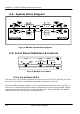
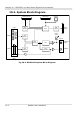
9.2. System Block Diagram
Fig 9-2: RB-SP1 System Block Diagram
9.3. Front Panel Indicators & Controls
Fig 9-3: RB-SP1 Front Panel
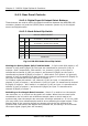
9.3.1. Front Panel LED’s
There are four LED indicators situated on the front of the unit. The red LED on the far
left of the front panel is to indicate that power is present on the unit.
The three LED’s grouped together on the right hand side have two roles, see Fig 5-3.
The first is to indicate the synchronisation frequencies of the incoming digital signals,
and the second is to flash when a signal has been lost. These indicators are labelled
individually to show the current sync frequencies.
TYPE
STEREO
MONO
96/48kHz
32kHz
88.2/44.1kHz
COMBINE
BYPASS
SPLIT
MODE
SPLIT
96