
Manual


Chapter 8 - RB-DMA2 Dual Digital Microphone Amplifier
8-6 Redbox User Handbook
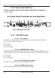
8.4.3.2. Output Routing
This uses switch 2 of the STATUS dipswitch block. When switch 2 is “ON”, the audio
signal from Mic input 1 is copied to both channels of the digital output signal (channel
B = channel A) and Mic input 2 is ignored (Dual mono mode). When “OFF”, the Mic
input 1 signal is on channel A only of the digital output signal and channel B contains
the Mic input 2 signal (Mono mode).
Note: This does not affect the routing of the analogue outputs.
8.4.3.3. Phantom Power & LF Filter
For each channel there are independent switches to provide phantom power at +48V
to the connected microphones. With phantom power selected, a voltage of +48V is
applied to pins 2 and 3 of the XLR connector to power the microphone, supplied
through 6k8 resistors giving a current of 14mA. Phantom power is used when the
switches are towards the arrows.
The LF filter switches provide control for a high pass filter with low frequency roll off
at 125Hz. The roll-off filters are switched “in” when the switches are in the down
position (towards the arrows).
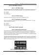
8.4.3.4. Digital Sync & Output Select Buttons
These buttons are used to switch the digital connection between the AES/EBU XLR
connector (button out) and the S/PDIF phono connector (button in) independently for
the digital sync input and the digital output.
Note: There is no switch to select the Word Clock as a sync input. The unit
automatically searches for a sync signal on the Word Clock, or the selected digital
input, and automatically locks to a valid sync clock.
8.4.3.5. Frequency and Sync Mode Rotary Switch
This rotary switch is used to select the Synchronisation Mode and to select the
frequency of the digital output when using the on-board clock generator. There are 4
modes of operation: - Master Mode, Auto Sync Mode, Auto Lock Sync Mode & Slave
Mode.
• In Master Sync Mode, switch positions 0 – 5, the digital output sample rate is
simply set by, and locked to, the internal on-board clock generator. No sync
signal is used or required.
• In Auto Sync Mode, switch positions 6– B, the digital output sample rate follows
the digital input. When the digital input signal is not present the output sample
rate will be set by, and locked to, the internal on-board clock generator at a
frequency determined by the switch position.
• In Auto-Lock Sync Mode, switch position C, No output will be generated until
lock is achieved with a digital input signal. The digital output sample rate now
follows the digital input. If the digital input signal is removed then the output
sample rate will be set by, and locked to, the internal on-board clock generator at
the closest frequency available to the previous digital input.